I took a bit of a different path than most. I did a custom design for all the control electronics within the case, rather than buy off the shelf pieces. The hardware is all complete, and games are playable. I just need to work on the software for my microcontroller to complete all finishing touches.
This is what I have so far:
-Original Wii U gamepad shell
-Push button power on/off using original power button
-Digital volume control
-Headphone jack
-SD card accessible at the case edge (I really don't want to open this thing again!)
-12v power input, allows for battery charging and playing at the same time
-All buttons and joysticks on the original Wii U gamepad are functional
What's on the inside:
-RPI3
-6.5inch HDMI screen
-Custom 7.4v 3650mAh battery pack (with protection board)
-Two 3650mAh flat LiPo packs in series
-Custom PIC18F87J50 microcontroller board
-Board contains the microcontroller for USB controller functionality. It also communicates with the audio amplifiers, battery monitor, and the buttons to control the screen menu.
-Custom PCM2706c USB audio
-Contained physically on the same board as the microcontroller. Provides audio output to the speaker and headphone amplifiers
-Custom Lion/LiPo battery charger and power path selection
-Based off the BQ24133 battery charger chip. Does automatic selection of battery versus 12v input for driving the Pi. Also allows for simultaneous charging and playing. The power board also includes a battery power gauge, and a cell balancer to keep the two batteries matched and happy.
-PTH08080 DC-DC converter for 5v rail to the Pi
-High efficiency power module for getting the 7.4v or 12v down to a stable 5v for the Pi and the screen
-Custom board with headphone amplifier and USB debug port to communicate with the microcontroller
-Custom board for the power, TV, and home buttons on the front panel
-Made the board to physically fit the exact same points as the existing board. Also added my own LEDs, and this board contains the speaker amplifiers.
-Rotary encoder wheel to implement digital volume selection and menu navigation
-No potentiometer here. Less wire routing of audio signals through the case, so less audio interference from unshielded wires. The digital wheel also will be repurposed as a navigation wheel for the screen menu.
Running Mario 64, the whole thing was drawing ~750mA at 7.4v. So with 3650mAh of capacity, that should give a theoretical run time of 4.85 hours. But realistically I think I can expect about 4 hours of run time.
Now on to some pictures. The camera on my phone isn't great, so I apologize for the picture quality. I also did not take many pictures of the whole build process. I was so focused on getting it all to work and to fit that I didn't think of documenting everything.
Pictures under spoiler tags since they're really big:
[spoiler="Final Product"]


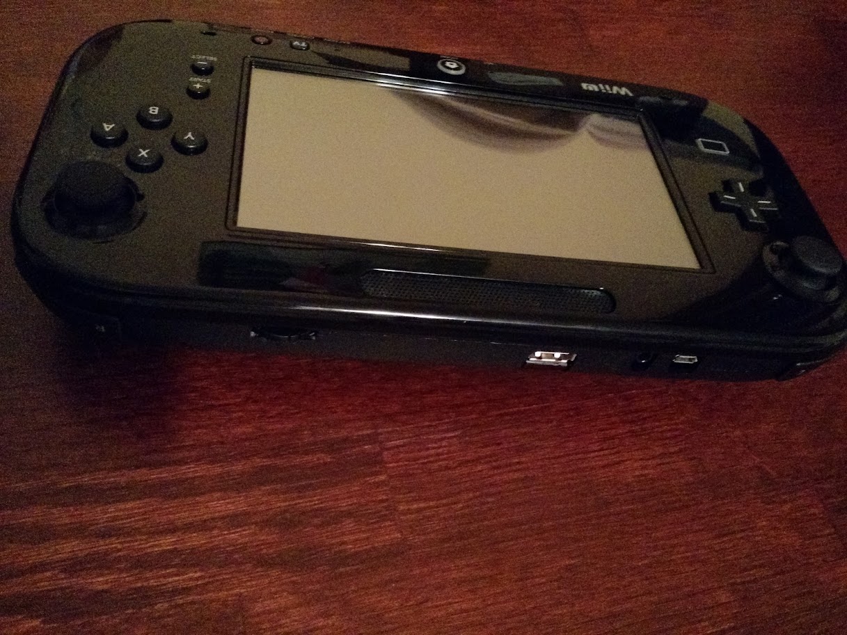 [/spoiler]
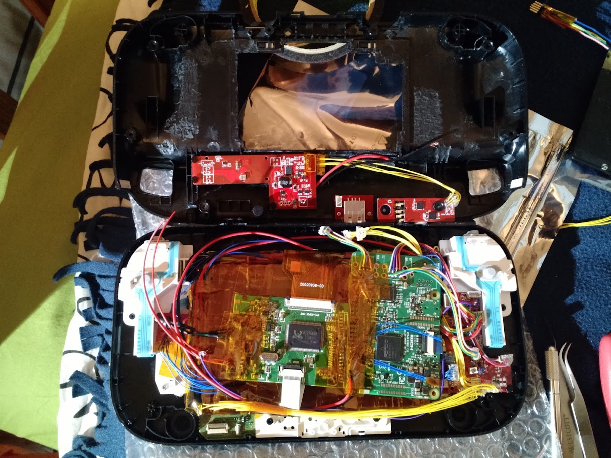
[spoiler="The Insides"]Original placement attempts. Two red boards up top are the power board (with charger and power regulator) and the headphone/USB debug board. The board on the right mounted to the white plastic is the microntroller and USB audio board.

Final placement of the RPi and screen driver board. Also shows the placement of the power board, headphone/USB debug board, and external USB port in the back half of the case
Getting the battery and everything finally wired up

Everything placed in the two halves of the case, ready to be closed up!

Different angle with everything placed, just showing how dense everything is in there
 [/spoiler]
[spoiler="Custom Boards"]I'll add more pictures of the other boards if anyone is interested. The only picture I have of a fully populated board is the button board that I made. I can take other pictures of the blank PCBs I have if anyone wants.
Button board that fits in the exact location as the original board. Also contains the speaker amplifiers
 [/spoiler]
Things left to do:
-Fully implement the battery status reading.
-Right now all the hardware is there, I just need to finish the software to read the battery status and display proper LED indicators
-Screen menu interaction
-Hardware is there, just need to finish software. When the TV button is pressed, the scroll wheel and home button will be used to navigate through the screen menu. This will allow me full access to change screen brightness, contrast, etc.
-Start playing games!
I was amazed when everything actually fit together and worked! I stayed up much too late getting it all finished
Updates on boards...
Everything was done in Eagle PCB. So hopefully anyone with that software can download and use/view any of the files. All the components have digikey part numbers and manufacturer part numbers as attributes. So you can easily generate a BOM for everything.
[spoiler="Main Boards"]The main boards contain my microcontroller L shaped board, a USB to UART and headphone amplifier board, the battery charger and power path selection, a 5V switching regulator, and some small FPC breakout boards.
Schematic:
https://drive.google.com/open?id=0B3oam ... Hdaa1M2N3c
Layout file:
https://drive.google.com/open?id=0B3oam ... nB3Ujd3MFU[/spoiler]
[spoiler="Button Board"]The button board is what went behind the home, TV and power buttons, replacing the original board. There are LEDs in the same places as on the original board, all with transistors to drive them. It also contains amplifiers for the speakers.
There's also two other small boards in the layout, a micro SD breakout board, and a board that held the rotary encoder I used as a volume wheel.
Schematic:
https://drive.google.com/open?id=0B3oam ... TRCQ3lTWW8
Layout file:
https://drive.google.com/open?id=0B3oam ... nZYR1g2d0k[/spoiler]
Feel free to ask for any clarifications on anything!


