Page 1 of 1
New Gear Best Screen Layout
Posted: Wed Jan 18, 2017 8:05 am
by tayman208
Hey everyone. I'm super new to this so bear with me.
I recently ordered a 3.5" screen from gearbest just like the one the wiki shows. However, the one I got has a slightly different layout on the board that the one pictured on the wiki.
As I do not want to fry my board, would anyone be able to show me where I should solder to make this one run off of 5v? Thanks a million. This forum is the best.
Re: New Gear Best Screen Layout
Posted: Wed Jan 18, 2017 1:33 pm
by Tristan
Re: New Gear Best Screen Layout
Posted: Tue Jan 31, 2017 12:22 am
by Johnputer
Hi, I got the same one you have. Basically I'm doing the same short as everyone else in the other versions, but I've followed the trace from the output pin on the voltage converter chip to a more solder-friendly location.
Haven't soldered it yet, but it worked on the bench when I supplied 5V to the pad - standard disclaimer, etc.
Enjoy!
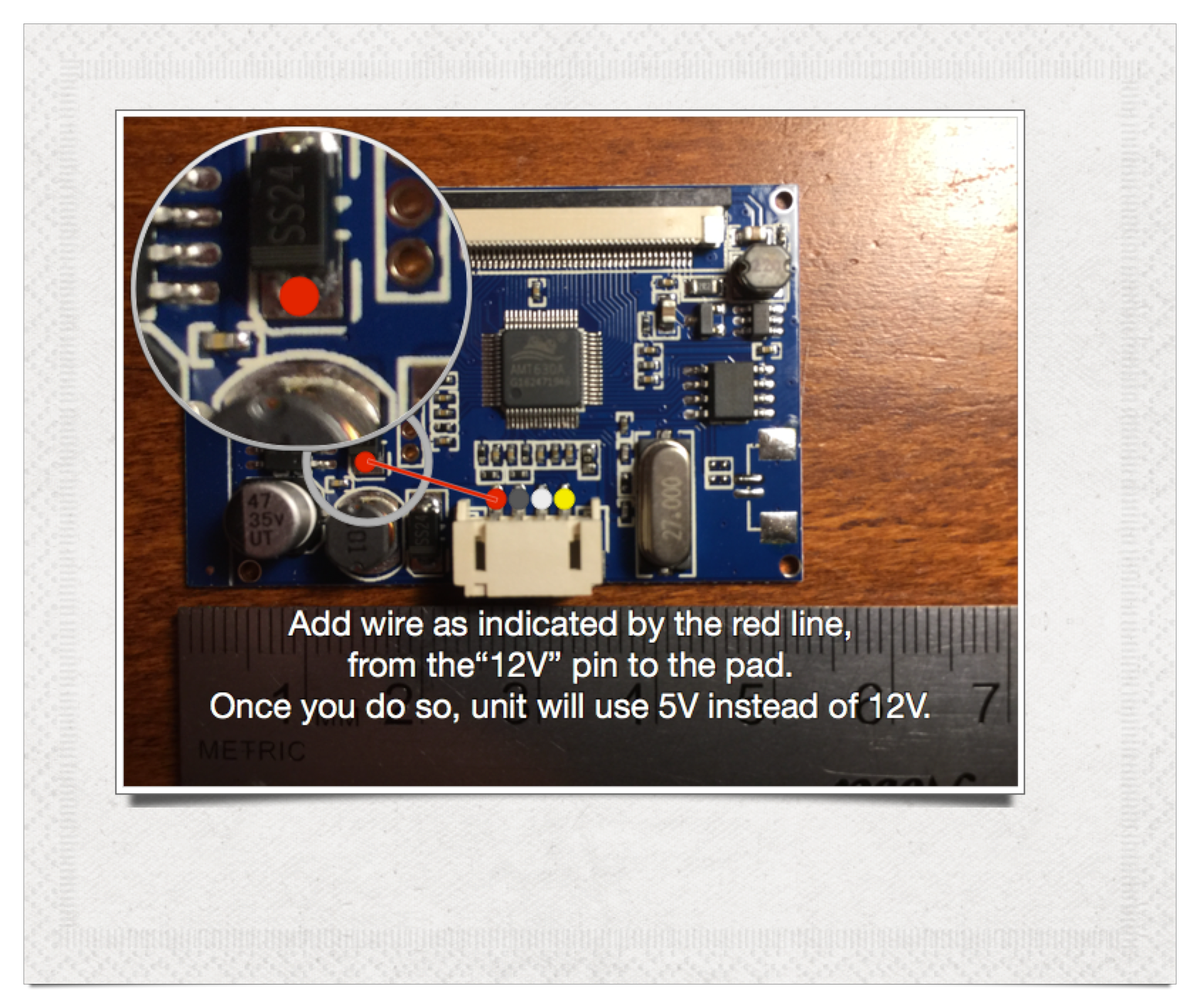
- gearbest_new_5V.png (2.95 MiB) Viewed 7832 times
Re: New Gear Best Screen Layout
Posted: Sat Feb 11, 2017 11:05 am
by xaman
Johnputer wrote:Hi, I got the same one you have. Basically I'm doing the same short as everyone else in the other versions, but I've followed the trace from the output pin on the voltage converter chip to a more solder-friendly location.
Haven't soldered it yet, but it worked on the bench when I supplied 5V to the pad - standard disclaimer, etc.
Enjoy!
gearbest_new_5V.png
Hi Johnputer! I have the same model from Gearbest. Have you soldered it following your scheme? Is it working? Thanks!!!!
Re: New Gear Best Screen Layout
Posted: Sat Feb 11, 2017 4:39 pm
by xaman
It's working! Thanks!

Re: New Gear Best Screen Layout
Posted: Sun Feb 12, 2017 7:19 pm
by Rabbitpuncher
Can I use any wire to solder this modification? Like a piece of the red wire from the lcd board?
Re: New Gear Best Screen Layout
Posted: Fri Mar 10, 2017 11:48 pm
by Johnputer
Rabbitpuncher wrote:Can I use any wire to solder this modification? Like a piece of the red wire from the lcd board?
Sure, any wire!
Re: New Gear Best Screen Layout
Posted: Sat Apr 29, 2017 4:46 pm
by tayman208
Thanks for the help! I did the mod (I think) and the screen powers on and runs well. However, the small text is blurry and almost unreadable. Anyone have any thoughts?
Also, are you soldering to the arm of that piece as shown in the diagram? or the pad to the right of it? I cant tell by your picture which you soldered it to. Is that what you were referring to by the "more solder friendly spot"?
Thanks again for the help. I love this forum.