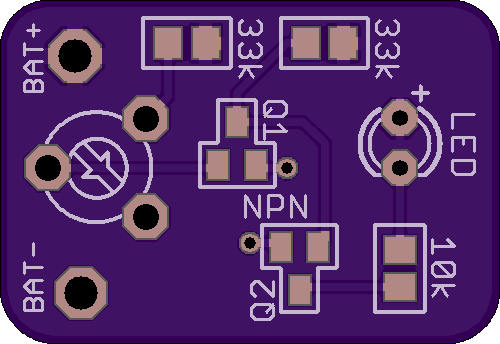
SMD Version:
https://oshpark.com/shared_projects/Q2XKys7X
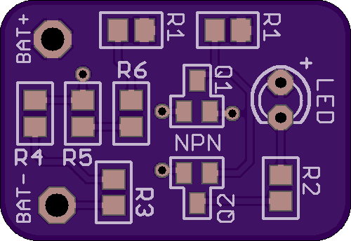
Parts list for this project:
Transistors:
http://www.taydaelectronics.com/t-trans ... b-215.html
33K Resistors:
http://www.taydaelectronics.com/resisto ... -0805.html
10K Resistor:
http://www.taydaelectronics.com/resisto ... -0805.html
47k Potentiometer (Variable Resistor):
http://www.taydaelectronics.com/potenti ... r-6mm.html
Red LED:
http://www.taydaelectronics.com/leds/ro ... m-red.html
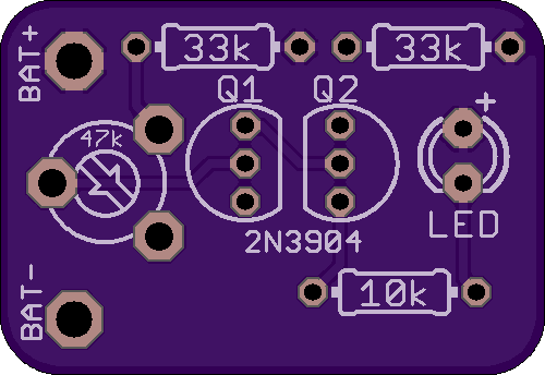
Through Hole Version:
https://oshpark.com/shared_projects/btIHScY7
Parts list for this project:
Transistors:
http://www.taydaelectronics.com/t-trans ... istor.html
33K Resistors:
http://www.taydaelectronics.com/resisto ... istor.html
10K Resistor:
http://www.taydaelectronics.com/resisto ... istor.html
47k Potentiometer (Variable Resistor):
http://www.taydaelectronics.com/potenti ... r-6mm.html
Red LED:
http://www.taydaelectronics.com/leds/ro ... m-red.html
Now the way this circuit works is the two transistors are configured as voltage sensor and inverter.
The first transistor on the left senses the threshold voltage level as per the setting of the 47K preset. As long as this transistor conducts, the second transistor on the right is held switched OFF, which also keeps the LED switched OFF.
As soon as the battery voltage falls below the set threshold level, the left transistor is no longer able to conduct.
This situation instantly triggers the right hand side transistor, switching ON the LED.
The LED switches ON and provides the required indications of a low battery warning.
-----------------------------------------------------------------------------------------------------------------------------------------------------
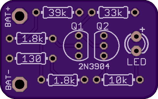
I got some solid values to make the board a little more low profile without the pot and it comes on at 3.26V so no need to tweak the pot.
SMD Version:
https://oshpark.com/shared_projects/KtfWqSdE
Through Hole Version:
https://oshpark.com/shared_projects/N6qwkU4V