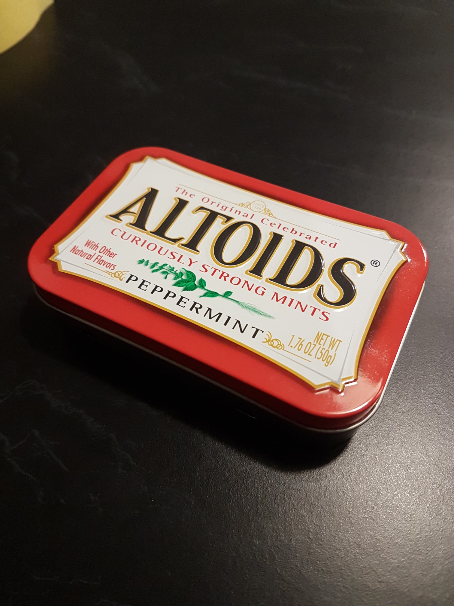
19/07 - Not that I'm letting the poll influence my decision...but decided to start with the Peppermint red!

- 20170719_222358-1512x2016.jpg (535.34 KiB) Viewed 16179 times
Just staying true to the guide

Drilling the trigger buttons holes was quick, but as Wermy advises start small and work your way up.

- 20170719_222522-1512x2016.jpg (513.34 KiB) Viewed 16179 times
As for the filing, I'll be honest, this took longer than expected and i miscalculated the noise level involved so spent the evening out in the shed


- 20170719_222503-1512x2016.jpg (507.97 KiB) Viewed 16179 times
Fixing the 3D print screen housing in place went perfectly. I dont actually have a roll of VHB tape but have pre-cut squares of it left over from dash cam mounts.

- 20170719_222133-1512x2016.jpg (595.45 KiB) Viewed 16179 times

- 20170719_222351-1512x2016.jpg (643.15 KiB) Viewed 16179 times
Test fitted the tactile buttons, power switch and micro USB charge cable to ensure all holes were correct.
That'll do for tonight

20/07 - Didnt have much time today but managed to mount the trigger buttons, solder the wires and glue in the base plate!

- 20170720_214305-1512x2016.jpg (697.44 KiB) Viewed 16048 times
22/07 - Time to work on the PCB / Screen - I'll be honest, had a couple of issues here although everything I needed was already on the forums.

Started off by soldering the PCB and Pi together as per the guide, even using those extra clamps to ensure there was no movement. 100% recommend a multi-meter here to test continuity.
Couple of holes needed a tad more soldering to make the connection but all went OK.

- 20170721_215510-1512x2016.jpg (955.68 KiB) Viewed 15955 times
I then trimmed the ribbon cable for the screen usung a scalpal which was easy enough. Didnt have much success locking the ribbon cable in using masking tape, however opted for a slither of electrical tape which worked a treat. (photo taken before i swapped!)

- IMG_20170722_173407.jpg (1.42 MiB) Viewed 15956 times
Upon completing had the 'white screen' as noted on the mintyPi hardware forum. Re-checked my soldering and the 5V was slightly temperamental so re-flowed that hole. Still found I had the white screen. Bit more reading up online and i went back to re-align my ribbon cable....success. Just needs to be placed nice and accurately.
Here it is working as expected:

- 20170722_131447-1512x2016.jpg (806.89 KiB) Viewed 15956 times
I also hooked up my USB sound card to test.

Have now prepped my soundcard for use inside the case along with the battery charger.

- IMG_20170722_173350.jpg (1.4 MiB) Viewed 15956 times
More to come.
28/07
Finished this build off! Had some white screen issues which are now rectified. Everything was plain sailing from there however

Except that is... trying to get solder to stick to the main GND pad was a pain!
As for the mintyPi itself, really impressed with how it all fits together and the screen is actually really impressive.

Thanks to Wermy and Helder for all of their efforts on this one. Such a great project.

Now to carry on with the other builds.....i note Wintergreen has nearly caught up in the poll

Here's a pic of the finished build:

- 20170728_003355-1512x2016.jpg (712.4 KiB) Viewed 15817 times


