
3.3V rail
Wiring Diagram: mintyPi controller PCB
-
Lphillimore

- Posts: 993
- Joined: Sat Jan 07, 2017 7:03 pm
- Location: Perth, WA
- Has thanked: 796 times
- Been thanked: 527 times
Re: Wiring Diagram: mintyPi controller PCB

mintyPi Giveaway [CLOSED]:
http://www.sudomod.com/forum/viewtopic.php?f=38&t=3456
Builds:
GBZ
http://www.sudomod.com/forum/viewtopic.php?f=9&t=2838
mintyPi
http://www.sudomod.com/forum/viewtopic.php?f=32&t=3468
Kite SAIO
http://www.sudomod.com/forum/viewtopic.php?f=9&t=3075
Dreamcast VMU
https://sudomod.com/forum/viewtopic.php ... 133#p62133

Re: Wiring Diagram: mintyPi controller PCB
I believe thats more of a convention thing to indicate which pad is #1 (don't think it connects to anything on the controller PCB).
-
Helder

- Trailblazer

- Posts: 2985
- Joined: Thu May 05, 2016 8:33 am
- Location: Rogers, AR
- Has thanked: 1459 times
- Been thanked: 3114 times
Re: Wiring Diagram: mintyPi controller PCB
It's there just for numbering and also to help align it knowing that square GPIO would be going there. That was a remnant of the previous versions before all the fancy silk screen was added.
Chat with me and other members On Discord
Don't contact me about obtaining my board files (as you will not get them). If my Boards or PCB Kits are sold out, they will be restocked as soon as I can get them and there is demand for them. You can join the mailing list on my Website to be notified when they are available.
Helder's Game Tech Website
We will not support any cloned work so don't come to us with technical issues to resolve, go talk to the cloner for help.
-
AnotherUsername
- Posts: 14
- Joined: Fri Aug 11, 2017 9:45 pm
- Has thanked: 4 times
- Been thanked: 6 times
Re: Wiring Diagram: mintyPi controller PCB
I noticed that in the Fritzing PCB diagram, the A button appears to be connected to pin 2, but on the printed board from this screenshot
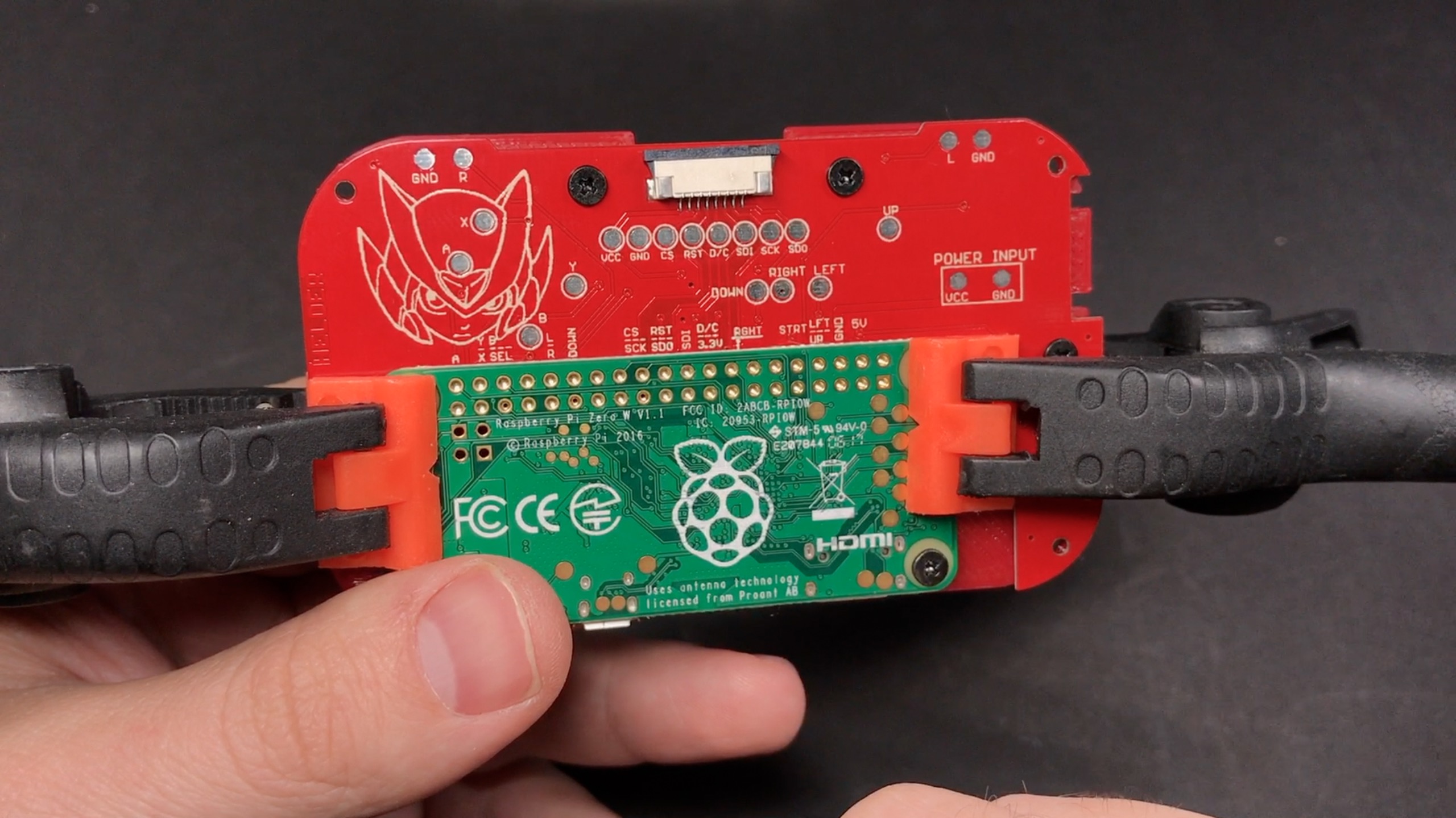
it looks like A is connected to pin 1. Am I looking at something wrong? I'm relatively new to wiring my own electronics and don't want to loose the magic smoke in all my new toys.
it looks like A is connected to pin 1. Am I looking at something wrong? I'm relatively new to wiring my own electronics and don't want to loose the magic smoke in all my new toys.
-
Helder
- Trailblazer
- Posts: 2985
- Joined: Thu May 05, 2016 8:33 am
- Location: Rogers, AR
- Has thanked: 1459 times
- Been thanked: 3114 times
Re: Wiring Diagram: mintyPi controller PCB
Pin 1 is the square GPIO on the bottom right.
Chat with me and other members On Discord
Don't contact me about obtaining my board files (as you will not get them). If my Boards or PCB Kits are sold out, they will be restocked as soon as I can get them and there is demand for them. You can join the mailing list on my Website to be notified when they are available.
Helder's Game Tech Website
We will not support any cloned work so don't come to us with technical issues to resolve, go talk to the cloner for help.
Don't contact me about obtaining my board files (as you will not get them). If my Boards or PCB Kits are sold out, they will be restocked as soon as I can get them and there is demand for them. You can join the mailing list on my Website to be notified when they are available.
Helder's Game Tech Website
We will not support any cloned work so don't come to us with technical issues to resolve, go talk to the cloner for help.
-
AnotherUsername
- Posts: 14
- Joined: Fri Aug 11, 2017 9:45 pm
- Has thanked: 4 times
- Been thanked: 6 times
-
Helder
- Trailblazer
- Posts: 2985
- Joined: Thu May 05, 2016 8:33 am
- Location: Rogers, AR
- Has thanked: 1459 times
- Been thanked: 3114 times
Re: Wiring Diagram: mintyPi controller PCB
The GPIO pins start from right to left the way the Pi is positioned in the photo above, and yes the A is the bottom GPIO on the left.
Chat with me and other members On Discord
Don't contact me about obtaining my board files (as you will not get them). If my Boards or PCB Kits are sold out, they will be restocked as soon as I can get them and there is demand for them. You can join the mailing list on my Website to be notified when they are available.
Helder's Game Tech Website
We will not support any cloned work so don't come to us with technical issues to resolve, go talk to the cloner for help.
Don't contact me about obtaining my board files (as you will not get them). If my Boards or PCB Kits are sold out, they will be restocked as soon as I can get them and there is demand for them. You can join the mailing list on my Website to be notified when they are available.
Helder's Game Tech Website
We will not support any cloned work so don't come to us with technical issues to resolve, go talk to the cloner for help.
-
AnotherUsername
- Posts: 14
- Joined: Fri Aug 11, 2017 9:45 pm
- Has thanked: 4 times
- Been thanked: 6 times
-
AnotherUsername
- Posts: 14
- Joined: Fri Aug 11, 2017 9:45 pm
- Has thanked: 4 times
- Been thanked: 6 times
Re: Wiring Diagram: mintyPi controller PCB
Edit: I've figured it all out using the posts in moosepr's signature, and via this topic: http://www.sudomod.com/forum/viewtopic.php?f=22&t=2312 Only thing I'm noticing is that the framerate is dropping pretty hard on my ili9431. I'm not sure if it's the nature of the screen, fbcp, or if I don't quite have the settings right. Tweaking with it now, any advice is appreciated! 
I'm sorry if this is an obvious question, I wasn't able to get any custom PCBs but I wanted to build a few of these to give away as groomsman gifts at my wedding.
I'm going based off of the Fritzing diagrams and all the photos and videos I can find on the forums. So far, I believe I've gotten all the pinouts figured out as to which button connects to which GPIO pin. The part where I get lost is when it's time to hook up the battery and charger. Does the VCC from the custom board plug directly to the 5v and 3.3v GPIO pins 4 and 17? I also wasn't sure if I needed to step the power up through something like the powerboost to get the 3.7v battery up to 5v, or if I can wire the battery directly to the GPIO pins.
I had to build this out of parts I could find, so I ended up with one of these chargers:

The battery will obviously plug into B+ and B-, but I'm not sure what to wire the OUT+ and OUT- to. I would think OUT- should go to the Pi's ground GPIO pin, but I have no idea...
I'm sorry if this is an obvious question, I wasn't able to get any custom PCBs but I wanted to build a few of these to give away as groomsman gifts at my wedding.
I'm going based off of the Fritzing diagrams and all the photos and videos I can find on the forums. So far, I believe I've gotten all the pinouts figured out as to which button connects to which GPIO pin. The part where I get lost is when it's time to hook up the battery and charger. Does the VCC from the custom board plug directly to the 5v and 3.3v GPIO pins 4 and 17? I also wasn't sure if I needed to step the power up through something like the powerboost to get the 3.7v battery up to 5v, or if I can wire the battery directly to the GPIO pins.
I had to build this out of parts I could find, so I ended up with one of these chargers:
The battery will obviously plug into B+ and B-, but I'm not sure what to wire the OUT+ and OUT- to. I would think OUT- should go to the Pi's ground GPIO pin, but I have no idea...
Who is online
Users browsing this forum: No registered users and 1 guest