Forum thread for discussion: https://sudomod.com/forum/viewtopic.php?f=13&t=5073
A couple things I forgot to mention this in the video:
The way the screen-flipping works is GPIO number 17 on the Pi is connected to one of the VMU connector pins. The corresponding pin in the controller is connected to ground. When the VMU turns on, a Python script runs that checks to see whether or not it’s plugged in. If it is, it updates the screen configuration to rotate the image. It increases the boot time a little if it needs to rotate it, but it’s nice and simple and works great. 🙂
The base RetroPie image I used is from the mintyPi, so it has HoolyHoo’s shortcut scripts (which I modified a bit for my this project) included for adjusting the volume/brightness (the the “Sleep”/Start button on the VMU is also the function button).
Here’s the RetroPie image: http://www.mediafire.com/file/nw8fggfvxvxmf1s/vmu.img.zip
Here is the Arduino code used in the controller (a modified version of the code I helped write for Helder’s AIO board): http://www.mediafire.com/file/uul8gd66w2v1hql/DC_Controller.zip
Here’s the STL file for the bracket I made: http://www.mediafire.com/file/0zc9cv2ejh9kvmi/vmu_bracket_microlipo.stl.zip
Parts list:
- Raspberry Pi Zero W
- 1.44″ SPI screen
- Micro-lipo from Adafruit
- i2S sound module from Adafruit
- 500mAh battery
- 13mm speaker
- Tactile Switches for L/R buttons
- Arduino Pro Micro knockoff
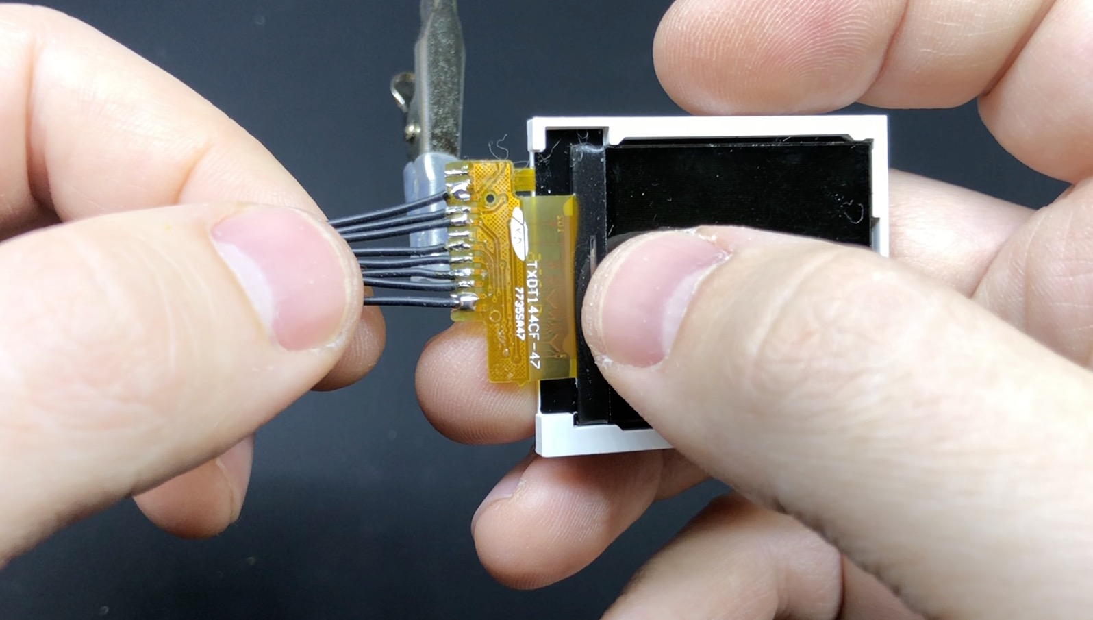
Screen pinout (pin number 1 is on bottom as shown above):
| Screen | Label | Pi |
|---|---|---|
| 1 | VCC | 3.3V |
| 2 | VCC | 3.3V |
| 3 | SDA | 10 |
| 4 | AO | 24 |
| 5 | CS | 8 |
| 6 | SCK | 11 |
| 8 | RST | 25 |
| 9 | LED | 13 |
| 10 | GND | GND |

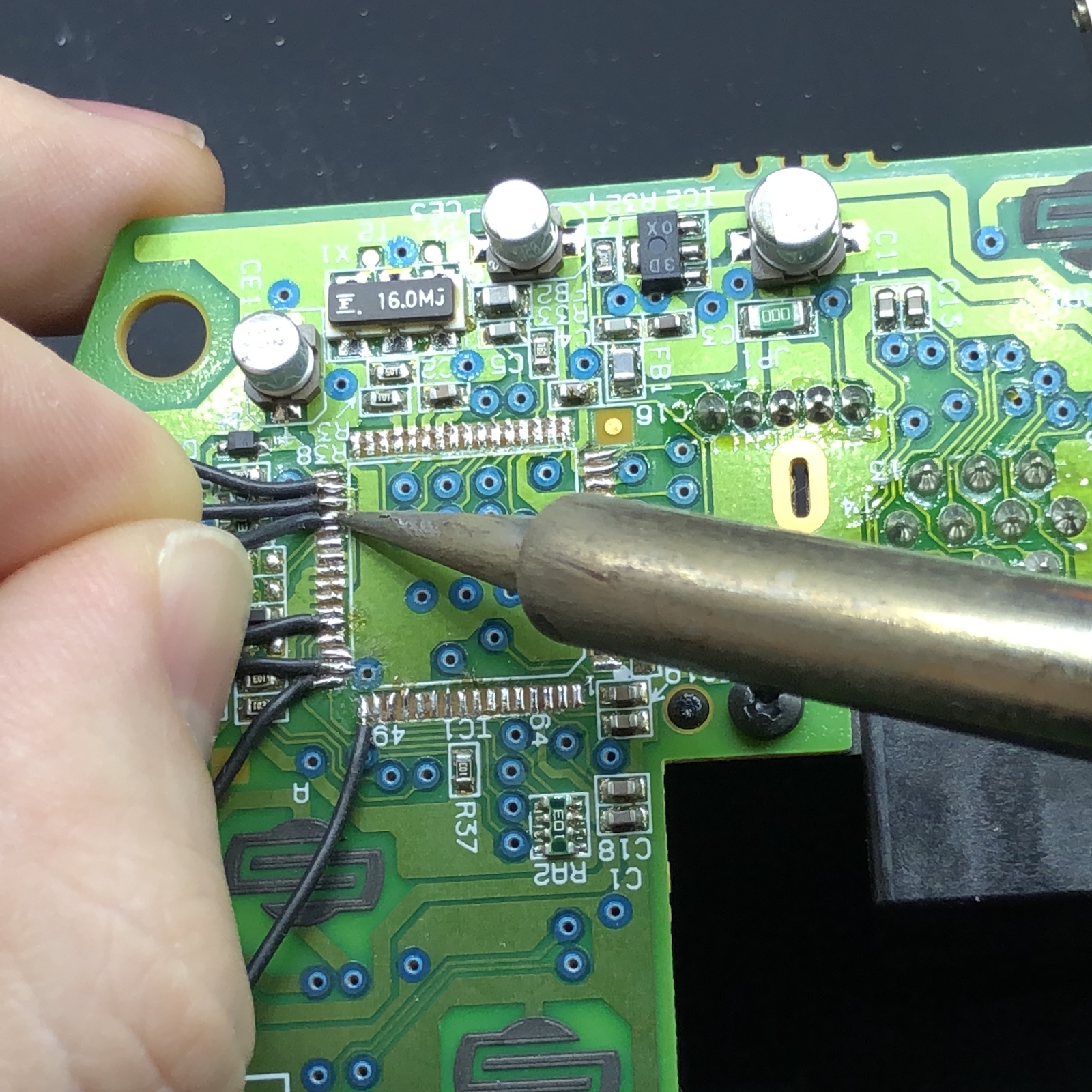
VMU PCB pins (from left to right as shown above, starting with the 4th from the left)
| Label | Pi |
|---|---|
| Sleep | 26 |
| Mode | 15 |
| B | 16 |
| A | 20 |
| Right | 22 |
| Left | 14 |
| Down | 5 |
| Up | 4 |
| GND (rightmost pin) | GND |
| L (tactile switch) | 12 |
| R (tactile switch) | 6 |
DC Controller (“Potato Chip”)
| Label | Potato Chip | Arduino |
|---|---|---|
| Up | 48 | 6 |
| Down | 49 | 2 |
| Left | 50 | 3 |
| Right | 51 | 4 |
| A | 52 | 5 |
| B | 44 | 8 |
| X | 36 | 10 |
| Y | 35 | 9 |
| L | 64 | A2 |
| R | 1 | A3 |
| Start | 47 | 7 |
| Stick-X | 62 | A0 |
| Stick-Y | 63 | A1 |
| 5V | 34 | VCC |
| GND | 2,3,4 | GND |
| Select (tactile switch) | N/A | 15 |