I do not have much soldering experience. So I laughed pretty hard when the super tiny FPC connectors came in the mail. But I was successful with a $5 soldering iron, so I thought I would share how I did it with any other inexperienced Sudomodders out there. Plus it gives me an excuse to use my clip-on macro lens for my phone. It basically went like this: tin the pads, hold the connector in place with the pins lined up with the pads and then re-melt the solder under the pins. This is probably basic stuff, but since there are a lot of different experience levels on this awesome forum, maybe it will help someone:
Connector:
https://www.amazon.com/gp/product/B016D ... UTF8&psc=1
Breakout Board:
https://www.amazon.com/gp/product/B014F ... UTF8&psc=1
[spoiler="Board and Connector with gigantic soldering iron tip"]
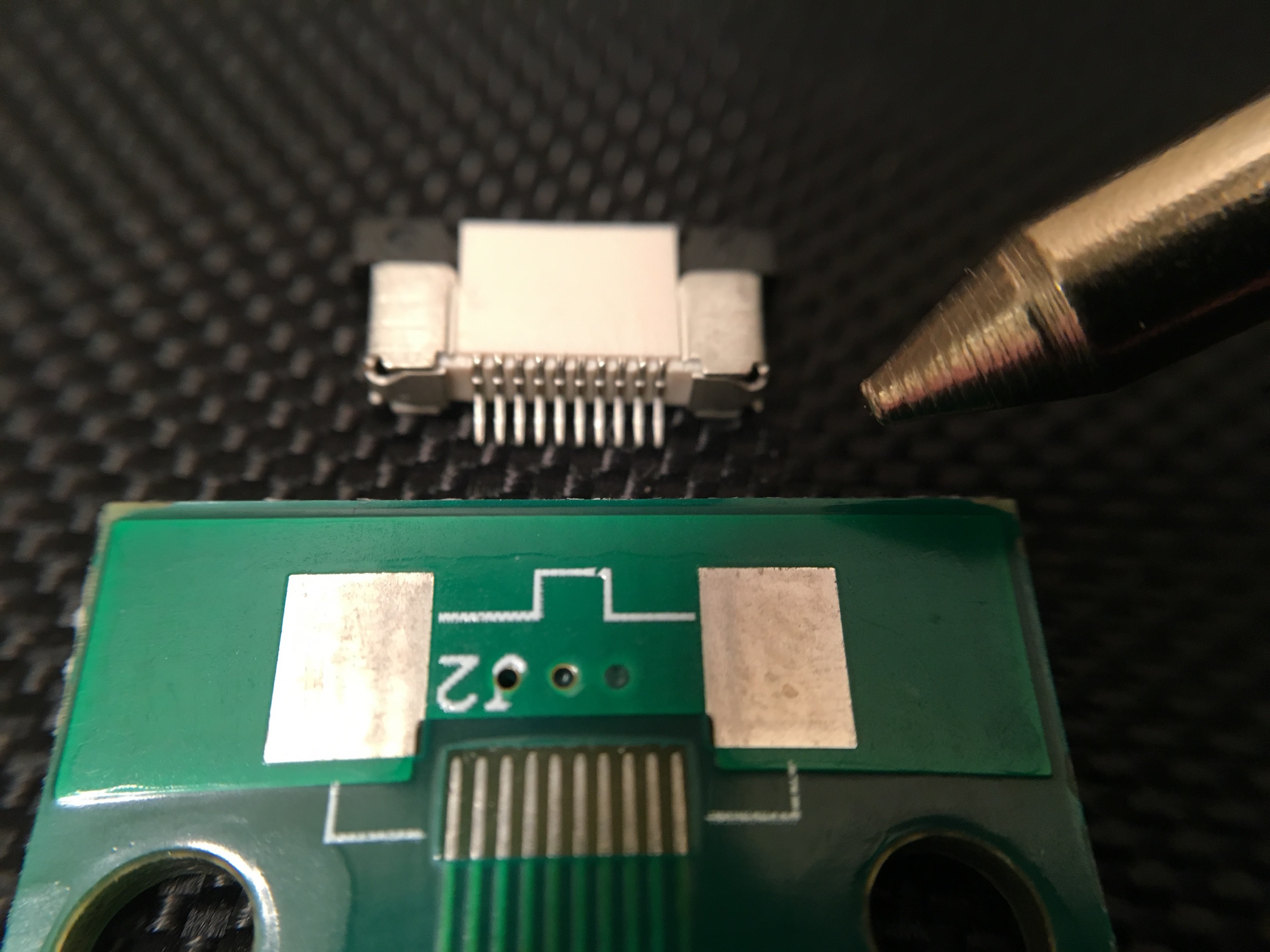
- IMG_9815.jpg (584.73 KiB) Viewed 11800 times
[/spoiler]
I used a little flux on the board and a drop of solder on my iron and ran it over the pads. The solder went to it's 'home' on the pads:
[spoiler="Tin the pads"]

- IMG_9833.jpg (72.99 KiB) Viewed 11800 times
[/spoiler]
Once the pads were tinned, I held the connecter in place with the pins/pads aligned. This was the tricky part since the pins wanted to slide between the soldered pads instead of resting on top.
[spoiler="Pins lined up"]

- IMG_9835.jpg (816.27 KiB) Viewed 11800 times
[/spoiler]
Then it was just a matter of re-melting the solder by running the iron on the pads. Make sure your tip is clean because any extra solder on there will want to flow up and bridge the pins. If that happens, you may be able to drag it back down from between the pins with your soldering iron. Once the pins are attached, you can solder the ends of the connector to the board to secure it.
[spoiler="Success"]
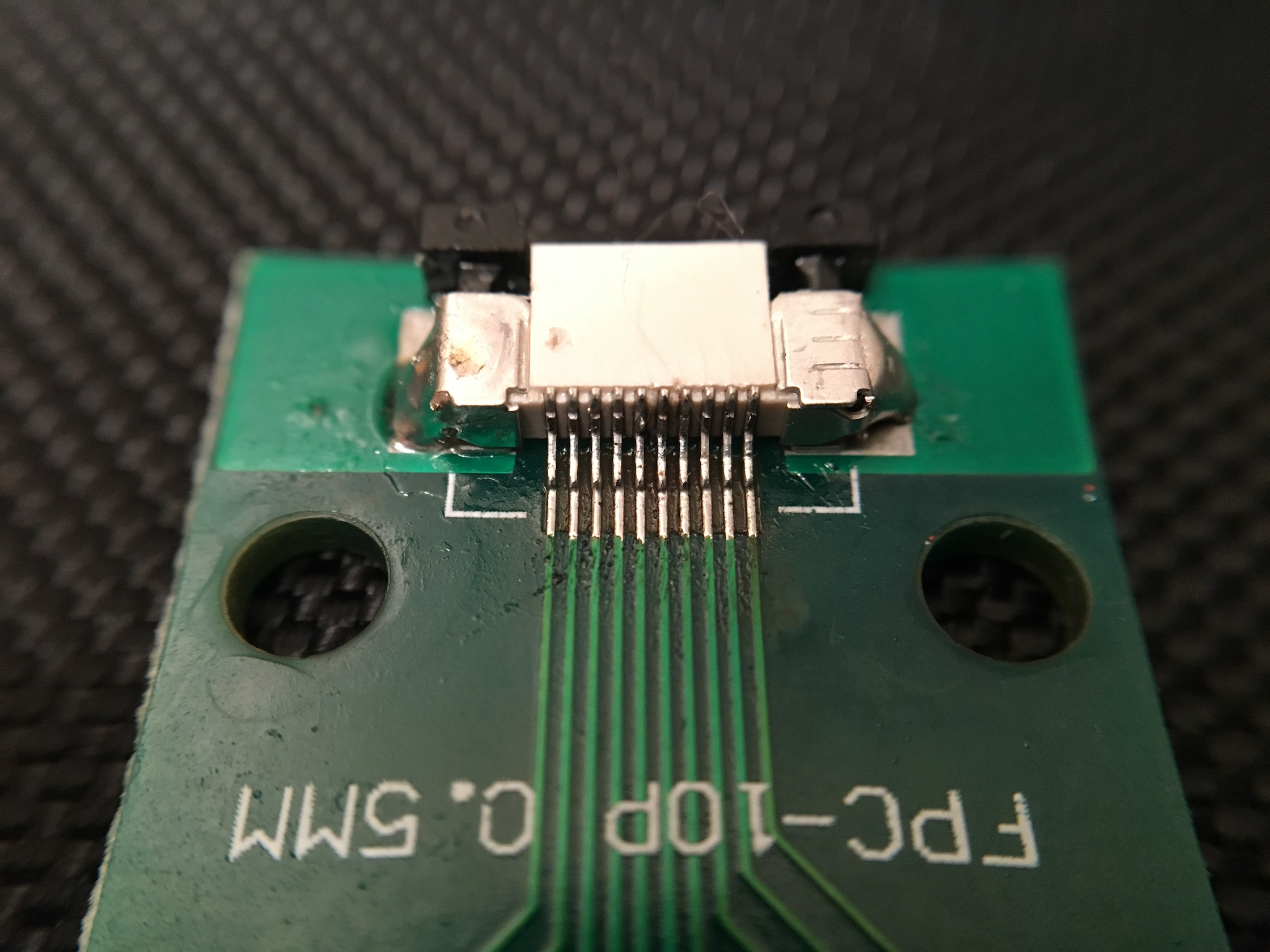
- IMG_9807.jpg (737.2 KiB) Viewed 11800 times
[/spoiler]
Hook it up to the Wii U gamepad and test all of the connections with your multimeter. I had to trim the little wings on the ribbon cable to get it to fit. The ribbon cable had to be inserted with the traces facing up to make contact with the pins inside this connector. Since the Wii U ribbon cable traces are only on the side that faces the screen, the breakout board will be 'upside down' against the back of the screen. This also means the trace numbering elsewhere on this forum is reversed with this board/connector combo.
[spoiler="Testing all of the connections and buttons"]
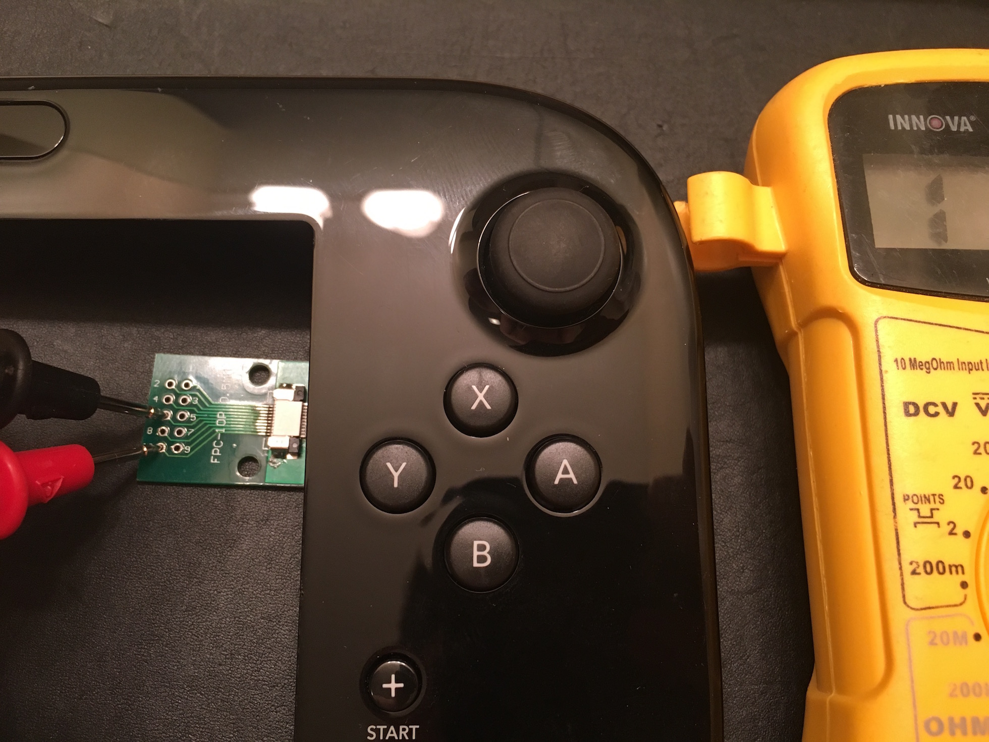
- IMG_9843.jpg (566.47 KiB) Viewed 11800 times
[/spoiler]
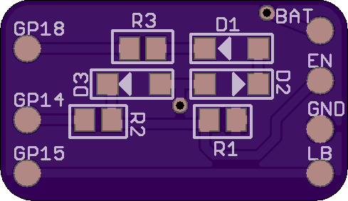
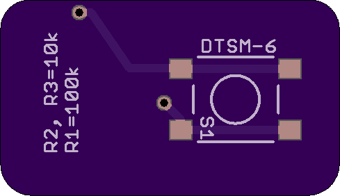
[spoiler="And here are the cable pinouts"]

- IMG_9823.JPG (827.54 KiB) Viewed 11739 times
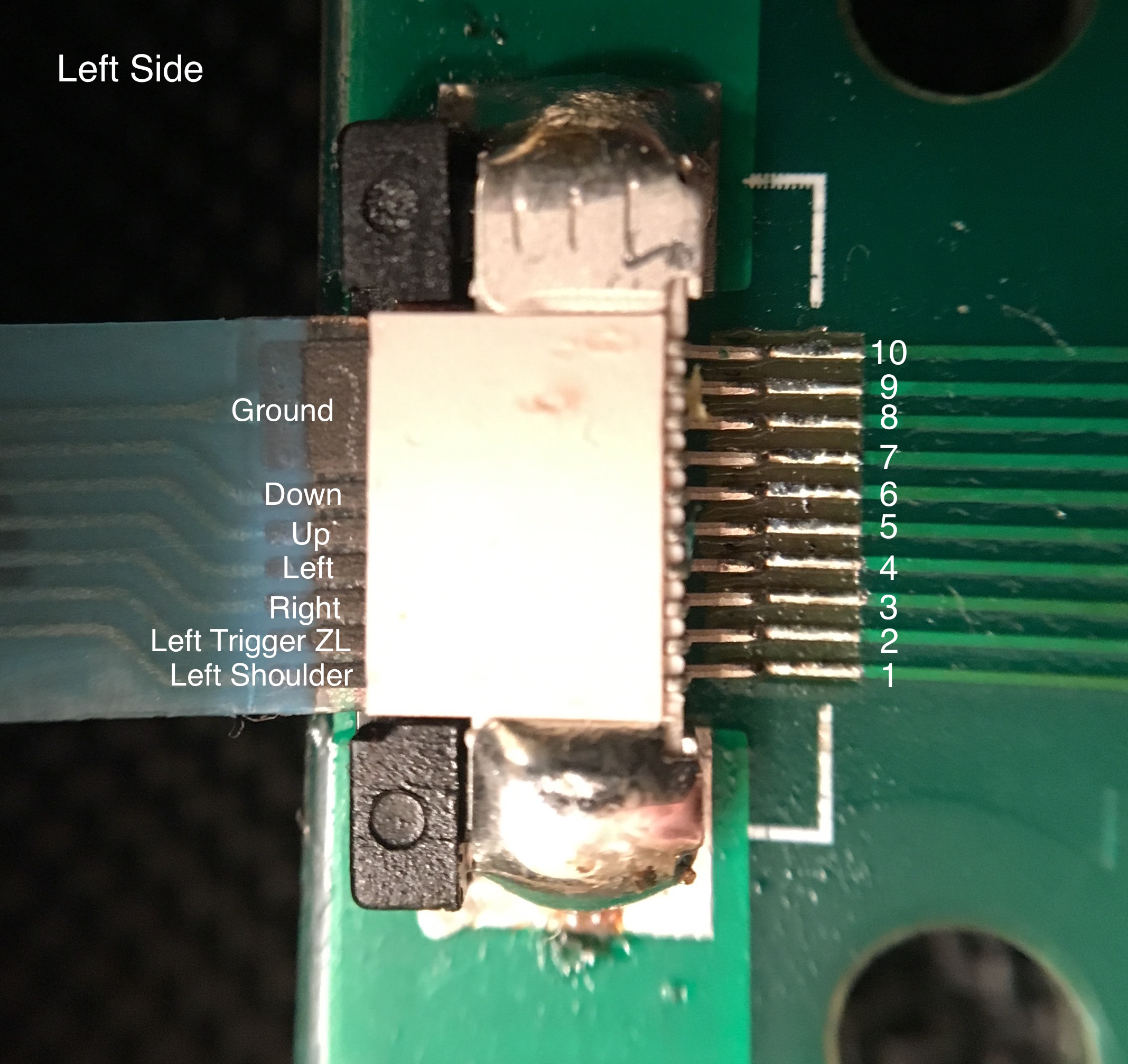
- IMG_9825.jpg (692.58 KiB) Viewed 11739 times
[/spoiler]
Anyway, I hope this helps. (Edited 11/12 to fix pinout labels.)