Page 1 of 3
HOW TO: Original GB Jack + Speaker setup
Posted: Sun May 15, 2016 11:40 am
by ktechelonbreak
Hey guys so I saw a few questions on the the forums about cutting power to the speakers when headphones are plugged into the jack. I've managed to find a solution using the original GB jack that is relatively clean so I'm here to share how I did it.
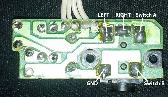
This is the pinout for the original jack, notice the 2 switch pads A and B.
This was how I did the GB jack setup:

You need to desolder Switch B so that it no longer has contact with Ground. Switch B is connected to Switch A, but only when no plug is connected. Red wire is (+) going to the speaker and black wire is (-) going to ground. Blue wire is from USB audio to L+R (I did mono sound to headphone rather than stereo. You can theoretically do stereo but the sound going to speaker will be mono). Blue/white wire is ground from USB audio. The orange wire is a bridge for L+R to Switch B. This means under normal conditions, the signal will go all the way to speakers but when headphone jack is inserted, the connection between Switch B and Switch A is cut, providing only signal to headphones.
EDIT: Ok guys, finally had some free time so I'm adding the wiring schematic I used in full here. This includes a pot that will control both speaker and headphone volume as well as the addition of the Adafruit amp.
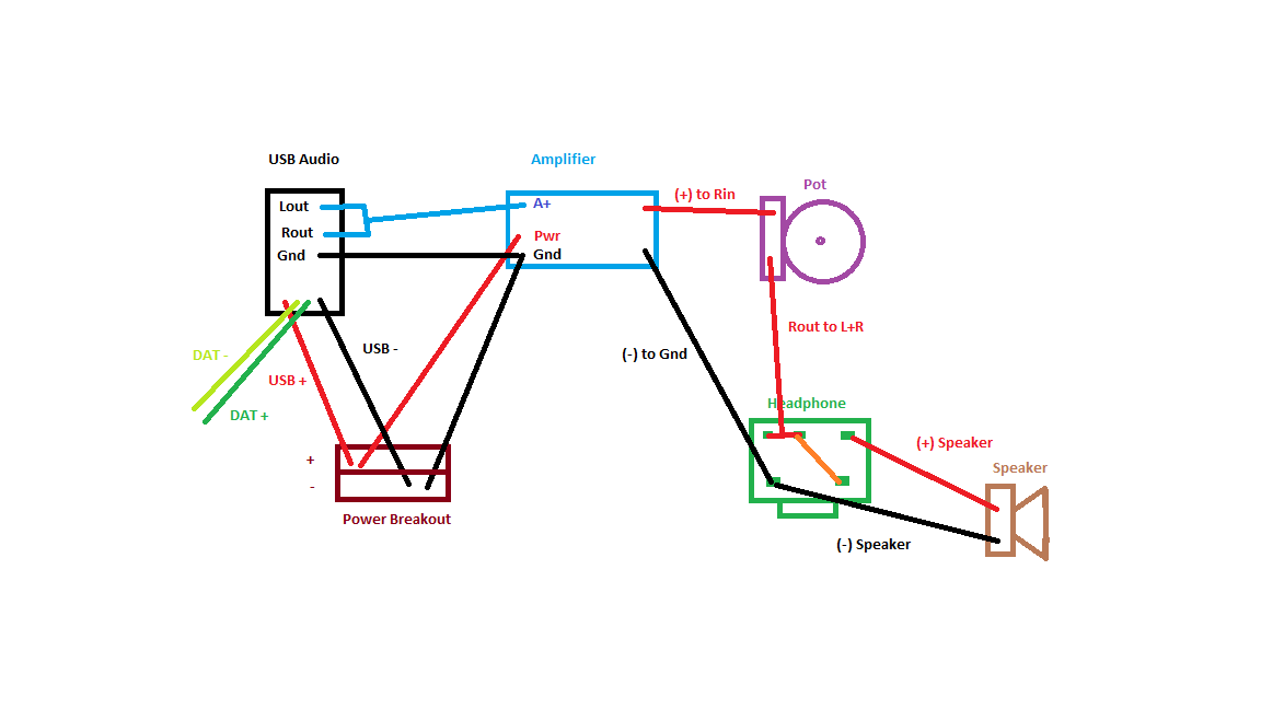
- SoundSetup.png (35.16 KiB) Viewed 15378 times
Re: HOW TO: Original GB jack + speaker setup
Posted: Sun May 15, 2016 2:06 pm
by grenade44
ktechelonbreak wrote:Hey guys so I saw a few questions on the the forums about cutting power to the speakers when headphones are plugged into the jack. I've managed to find a solution using the original GB jack that is relatively clean so I'm here to share how I did it.
This is the pinout for the original jack, notice the 2 switch pads A and B.
This was how I did the GB jack setup:
You need to desolder Switch B so that it no longer has contact with Ground. Switch B is connected to Switch A, but only when no plug is connected. Red wire is (+) going to the speaker and black wire is (-) going to ground. Blue wire is from USB audio to L+R (I did mono sound to headphone rather than stereo. You can theoretically do stereo but the sound going to speaker will be mono). Blue/white wire is ground from USB audio. The orange wire is a bridge for L+R to Switch B. This means under normal conditions, the signal will go all the way to speakers but when headphone jack is inserted, the connection between Switch B and Switch A is cut, providing only signal to headphones.
Thanks for this, also any idea how to wire the volume wheel to this setup?
Re: HOW TO: Original GB jack + speaker setup
Posted: Sun May 15, 2016 9:34 pm
by ktechelonbreak
You could have the L+R output from USB to pot L or R, then output that to the headphones. I'd still have the USB ground go straight to the headphone ground. If using an amplifier, I'd put the pot after the mono sound out from the amplifier.
Re: HOW TO: Original GB jack + speaker setup
Posted: Sun May 15, 2016 9:40 pm
by Kilren
Awesome work. Nice and clear directions. You should get this posted under hardware>guides
Re: HOW TO: Original GB jack + speaker setup
Posted: Sun May 15, 2016 11:29 pm
by crispy_tofu
Thanks for sharing, this is very useful!

Re: HOW TO: Original GB jack + speaker setup
Posted: Mon May 16, 2016 7:40 am
by Ganreizu
Only thing missing from this is a wiring schematic! I'd like to do this with an amplifier but was confused at that explanation. A visual would be amazing. Thanks for the guide
Re: HOW TO: Original GB jack + speaker setup
Posted: Tue May 17, 2016 12:18 am
by crispy_tofu
Kilren wrote:Awesome work. Nice and clear directions. You should get this posted under hardware>guides
Looks like that's been done, thanks mods!
Re: HOW TO: Original GB jack + speaker setup
Posted: Wed May 18, 2016 7:11 pm
by Mad_Duke
Hei!
I'm lost.
How would you do stereo with this setup? Also, has anyone managed to connect the volume wheel to this?
Should it be
Audio out -> Volume wheel -> the original PCB with a headphone jack and a speaker connected to it? Or something else?
I'm guessing if using and amplifier it would just go between the original PCB (this small one with the heapdhone jack) and the speaker?
Re: HOW TO: Original GB Jack + Speaker setup
Posted: Tue May 24, 2016 9:24 am
by ktechelonbreak
Bump, updated to include a schematic.
Re: HOW TO: Original GB Jack + Speaker setup
Posted: Tue May 24, 2016 4:00 pm
by grenade44
ktechelonbreak wrote:Bump, updated to include a schematic.
Thanks for the schematic, does your speaker cut out when headphone are plugged in and then back to speaker after headphones are removed?
Im using this amp
https://www.sparkfun.com/products/11044
I can get the volume working and either the speaker on its own or the headphones on its own but when i connect them all together i cant get both to work. Im sure ive followed your wiring but the only difference is that the volume wheel has its own pins on the amp and the two output pins as well. any ideas?