Fantastic! I got it going, I think my problem was the crystals and it's connect capacitors. I tried a blank board and used a higher pf value and it all worked.
Thank you my good man.
Some HELP with programming an Atmega32U4 with ISP
-
Helder

- Trailblazer

- Posts: 2985
- Joined: Thu May 05, 2016 8:33 am
- Location: Rogers, AR
- Has thanked: 1459 times
- Been thanked: 3114 times
Re: Some HELP with programming an Atmega32U4 with ISP
Chat with me and other members On Discord
Don't contact me about obtaining my board files (as you will not get them). If my Boards or PCB Kits are sold out, they will be restocked as soon as I can get them and there is demand for them. You can join the mailing list on my Website to be notified when they are available.
Helder's Game Tech Website
We will not support any cloned work so don't come to us with technical issues to resolve, go talk to the cloner for help.
-
Poppy McDoh!
- Posts: 10
- Joined: Tue Aug 30, 2016 2:46 am
- Location: Germany
- Has thanked: 1 time
- Been thanked: 5 times
Re: Some HELP with programming an Atmega32U4 with ISP
@tronicgr could you help me please?
i read your posts about the oxodao-code...
i have no clue about this part in my code-mod, where i added some buttons and changed the pin order:
the problem: i got some pro micro clones with arduino leonardo bootloader already flashed and i don't want to flash them again, so i have to change the code (i think so...!?!?).
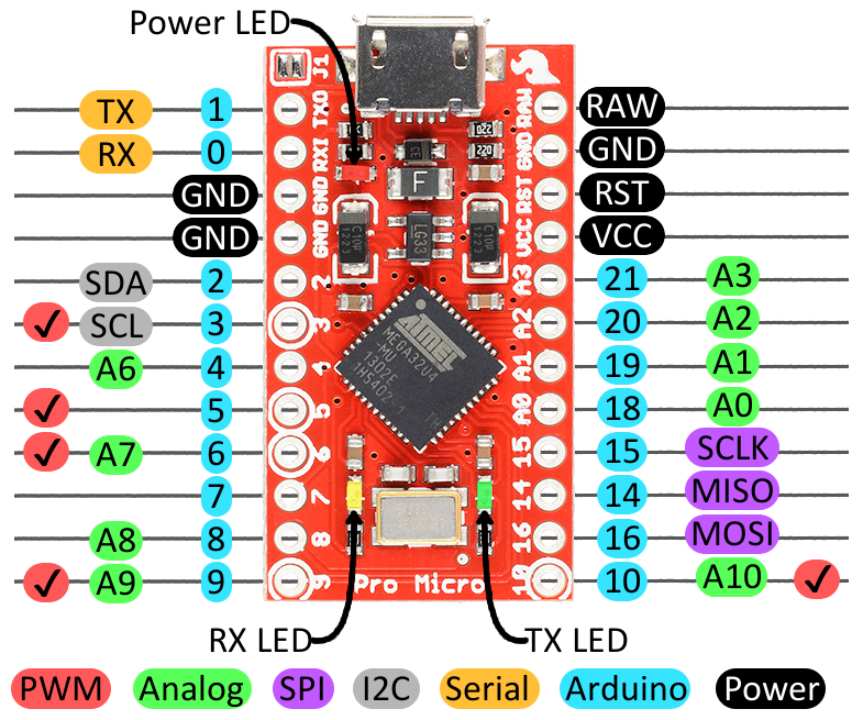
on the pro-micro-pcb i DON'T want to occupy pin 16 MOSI, 14 MISO, 15 SLK due to reprogramming reasons (if bootloader fails ...). so i have to use pins higher than pin#16 but i don't know how to chaged the define commands correctly. i think the number behind the define command is the pin port???
pins 11, 12, 13 in original pro micro layout can't be used for diginal i/o. so i can't explain, why oxodao used 11, 12, 13 in his code
layout on my pro micro clones is the same as original one from sparkfun:
original code with void setup correction:
my code-mod:
i read your posts about the oxodao-code...
i have no clue about this part in my code-mod, where i added some buttons and changed the pin order:
Code: Select all
void setup() {
  for (int x = 0; x<14; x++){
pinMode(x, INPUT_PULLUP);on the pro-micro-pcb i DON'T want to occupy pin 16 MOSI, 14 MISO, 15 SLK due to reprogramming reasons (if bootloader fails ...). so i have to use pins higher than pin#16 but i don't know how to chaged the define commands correctly. i think the number behind the define command is the pin port???
pins 11, 12, 13 in original pro micro layout can't be used for diginal i/o. so i can't explain, why oxodao used 11, 12, 13 in his code
layout on my pro micro clones is the same as original one from sparkfun:
original code with void setup correction:
Code: Select all
#include <Gamepad.h>
Gamepad gb;

#define BTN_DOWN 1
#define BTN_UP 0
#define BTN_LEFT 2
#define BTN_RIGHT 3
#define BTN_A 4
#define BTN_START 5
#define BTN_Y 6
#define BTN_L1 7
#define BTN_X 8
#define BTN_R1 9
#define BTN_R2 10
#define BTN_L2 11
#define BTN_B 12
#define BTN_SELECT 13

void setup() {
  for (int x = 0; x<14; x++){
      pinMode(x, INPUT_PULLUP);
  }
}

void loop() {

  bool downSet  = digitalRead(BTN_DOWN);
  bool upSet    = digitalRead(BTN_UP); // No pun intended
  bool leftSet  = digitalRead(BTN_LEFT);
  bool rightSet = digitalRead(BTN_RIGHT);

  gb.setLeftXaxis(!leftSet ? -127 : !rightSet ? 127 : 0);
  gb.setLeftYaxis(!downSet ? 127 : !upSet ? -127 : 0);

  gb.setButtonState(1, !digitalRead(BTN_A));
  gb.setButtonState(2, !digitalRead(BTN_B));
  gb.setButtonState(3, !digitalRead(BTN_X));
  gb.setButtonState(4, !digitalRead(BTN_Y));
  gb.setButtonState(5, !digitalRead(BTN_SELECT));
  gb.setButtonState(6, !digitalRead(BTN_START));
  gb.setButtonState(7, !digitalRead(BTN_L1));
  gb.setButtonState(8, !digitalRead(BTN_R1));
  gb.setButtonState(9, !digitalRead(BTN_L2));
  gb.setButtonState(10, !digitalRead(BTN_R2));

  gb.sendUpdate();
}
Code: Select all
#include <Gamepad.h>
Gamepad gb;

// changed button order due to older helder button pcb and added some new buttons (turbo / slow)
#define BTN_A 1
#define BTN_B 0
#define BTN_Y 2
#define BTN_X 3

#define BTN_START 4
#define BTN_SELECT 5

#define BTN_RIGHT 6
#define BTN_DOWN 7
#define BTN_UP 8
#define BTN_LEFT 9

#define BTN_L1 10
#define BTN_R1 11
#define BTN_L2 12
#define BTN_R2 13

#define BTN_TURBO 14
#define BTN_SLOW 15

// previously <14 with 14 buttons (0-13). now changed to <16 with 16 buttons (0-15):
void setup() {
  for (int x = 0; x<16; x++){
      pinMode(x, INPUT_PULLUP);
  }
}

void loop() {

  bool rightSet = digitalRead(BTN_RIGHT);
  bool downSet  = digitalRead(BTN_DOWN);
  bool upSet    = digitalRead(BTN_UP);
  bool leftSet  = digitalRead(BTN_LEFT);

  gb.setLeftXaxis(!leftSet ? -127 : !rightSet ? 127 : 0);
  gb.setLeftYaxis(!downSet ? 127 : !upSet ? -127 : 0);

// changed button output:
  gb.setButtonState(2, !digitalRead(BTN_A));
  gb.setButtonState(1, !digitalRead(BTN_B));
  gb.setButtonState(3, !digitalRead(BTN_Y));
  gb.setButtonState(4, !digitalRead(BTN_X));
  gb.setButtonState(10, !digitalRead(BTN_START));
  gb.setButtonState(9, !digitalRead(BTN_SELECT));
  gb.setButtonState(5, !digitalRead(BTN_L1));
  gb.setButtonState(6, !digitalRead(BTN_R1));
  gb.setButtonState(7, !digitalRead(BTN_L2));
  gb.setButtonState(8, !digitalRead(BTN_R2));
  gb.setButtonState(11, !digitalRead(BTN_TURBO));
  gb.setButtonState(12, !digitalRead(BTN_SLOW));

  gb.sendUpdate();
}
-
Camble

- Posts: 885
- Joined: Thu May 05, 2016 2:31 am
- Location: Scotland
- Has thanked: 269 times
- Been thanked: 488 times
Re: Some HELP with programming an Atmega32U4 with ISP
This code simply loops round from 0 to 13 and sets each pin to a pull-up. Grounding the pin represents a button press.Poppy McDoh! wrote:help
Code: Select all
void setup() {
  for (int x = 0; x<14; x++) {
    pinMode(x, INPUT_PULLUP);
  }
}
Code: Select all
pinMode(11, INPUT_PULLUP);
pinMode(12, INPUT_PULLUP);

pinMode(17, INPUT_PULLUP);
pinMode(18, INPUT_PULLUP);
Code: Select all
void setup() {
  for (int x = 0; x<14; x++) {
    pinMode(x, INPUT_PULLUP);
  }
  for (int y = 17; y<20; y++) {
    pinMode(y, INPUT_PULLUP);
  }
}
-
Poppy McDoh!
- Posts: 10
- Joined: Tue Aug 30, 2016 2:46 am
- Location: Germany
- Has thanked: 1 time
- Been thanked: 5 times
Re: Some HELP with programming an Atmega32U4 with ISP
so to remove the void setup code just replace it with this?
do you have an idea how i can handle the 16 MOSI, 14 MISO, 15 SLK pins?
Code: Select all
pinMode(1, INPUT_PULLUP);
pinMode(0, INPUT_PULLUP);
pinMode(2, INPUT_PULLUP);
pinMode(3, INPUT_PULLUP);

pinMode(4, INPUT_PULLUP);
pinMode(5, INPUT_PULLUP);

pinMode(6, INPUT_PULLUP);
pinMode(7, INPUT_PULLUP);
pinMode(8, INPUT_PULLUP);
pinMode(9, INPUT_PULLUP);

pinMode(10, INPUT_PULLUP);
pinMode(11, INPUT_PULLUP);
pinMode(12, INPUT_PULLUP);
pinMode(13, INPUT_PULLUP);

pinMode(14, INPUT_PULLUP);
pinMode(15, INPUT_PULLUP);-
Camble
- Posts: 885
- Joined: Thu May 05, 2016 2:31 am
- Location: Scotland
- Has thanked: 269 times
- Been thanked: 488 times
Re: Some HELP with programming an Atmega32U4 with ISP
Sure, it'll do the same thing. You can just omit the pins you don't want to configure.Poppy McDoh! wrote:so to remove the void setup code just replace it with this?
-
Poppy McDoh!
- Posts: 10
- Joined: Tue Aug 30, 2016 2:46 am
- Location: Germany
- Has thanked: 1 time
- Been thanked: 5 times
Re: Some HELP with programming an Atmega32U4 with ISP
for line
i get this error in arduino ide:
exit status 1
expected constructor, destructor, or type conversion before '(' token
do you have an idea what this means?
Code: Select all
pinMode(15, INPUT_PULLUP);exit status 1
expected constructor, destructor, or type conversion before '(' token
do you have an idea what this means?
-
Poppy McDoh!
- Posts: 10
- Joined: Tue Aug 30, 2016 2:46 am
- Location: Germany
- Has thanked: 1 time
- Been thanked: 5 times
Re: Some HELP with programming an Atmega32U4 with ISP
solved by adding void setup command:
####################
now i loaded the sketch onto the arduino leonardo. everything compiled fine and upload was successful. now windows detects the usb device again and tries to install a driver for it (should be HID gamepad...!?) but the driver installation fails after several minutes.
i sticked the board into another usb port. now windows does not detect anything! dead. but how can this be???
####################
update:
solved by re-flashing it with "Bootflash_program_gameboy.hex". now its being detected as sparkfun pro micro.
Code: Select all
void setup()
// activate pullups:
{
pinMode(1, INPUT_PULLUP);
pinMode(0, INPUT_PULLUP);
pinMode(2, INPUT_PULLUP);
pinMode(3, INPUT_PULLUP);

pinMode(4, INPUT_PULLUP);
pinMode(5, INPUT_PULLUP);

pinMode(6, INPUT_PULLUP);
pinMode(7, INPUT_PULLUP);
pinMode(8, INPUT_PULLUP);
pinMode(9, INPUT_PULLUP);

pinMode(10, INPUT_PULLUP);
pinMode(11, INPUT_PULLUP);
pinMode(12, INPUT_PULLUP);
pinMode(13, INPUT_PULLUP);

pinMode(14, INPUT_PULLUP);
pinMode(15, INPUT_PULLUP);

}now i loaded the sketch onto the arduino leonardo. everything compiled fine and upload was successful. now windows detects the usb device again and tries to install a driver for it (should be HID gamepad...!?) but the driver installation fails after several minutes.
i sticked the board into another usb port. now windows does not detect anything! dead. but how can this be???
####################
update:
solved by re-flashing it with "Bootflash_program_gameboy.hex". now its being detected as sparkfun pro micro.
Last edited by Poppy McDoh! on Tue Oct 25, 2016 7:10 am, edited 2 times in total.
-
Poppy McDoh!
- Posts: 10
- Joined: Tue Aug 30, 2016 2:46 am
- Location: Germany
- Has thanked: 1 time
- Been thanked: 5 times
Re: Some HELP with programming an Atmega32U4 with ISP
now i loaded the sparkfun pro micro settings in arduino ide and flashed my code to the chip. it works. but somehow the button allocation is not what i want to send. for example receiving "11" and "12" in windows/gamecontrollersettings when pressing BTN_TURBO or BTN_SLOW does not work at all!
any idea for this? here are the windows gamecontroller values i want to receive when pressing the different buttons. up, down, left, right works fine at the right pins! the other pins are mixed or do not work
##########
update:
solved by changing whole pin layout and mapping.
any idea for this? here are the windows gamecontroller values i want to receive when pressing the different buttons. up, down, left, right works fine at the right pins! the other pins are mixed or do not work
##########
update:
solved by changing whole pin layout and mapping.
- Attachments
-
- pinout-pro-micro.jpg (199.47 KiB) Viewed 20421 times
-
Poppy McDoh!
- Posts: 10
- Joined: Tue Aug 30, 2016 2:46 am
- Location: Germany
- Has thanked: 1 time
- Been thanked: 5 times
Re: Some HELP with programming an Atmega32U4 with ISP
@ tronicgr: why did you set the E fuse to the following value?
L 0xFF <- OK
H 0xD8 <- OK
E 0xCB <- WHY?
this setting means that BROWN OUT DETECTION is activated at 2.6V
have a look: http://www.engbedded.com/fusecalc
voltage via USB will always be at 5V, so why is BOD enabled? and why 2.6V? is it necessary?
if you disable BOD (value = CF / FF) you can save some more current.
also remove the LED and the voltage regulator from the "pro micro pcb".
thats almost the same procedure as for the 328P boards: https://andreasrohner.at/posts/Electron ... nsumption/
some hints from the Atmega32u4 datasheet:
If the Brown-out Detector is enabled by the BODLEVEL Fuses, it will be enabled in all sleep modes, and hence, always consume
power. In the deeper sleep modes, this will contribute significantly to the total current consumption.
Preventing EEPROM Corruption
During periods of low VCC, the EEPROM data can be corrupted because the supply voltage is too low for the
CPU and the EEPROM to operate properly. These issues are the same as for board level systems using
EEPROM, and the same design solutions should be applied.
An EEPROM data corruption can be caused by two situations when the voltage is too low. First, a regular write
sequence to the EEPROM requires a minimum voltage to operate correctly. Secondly, the CPU itself can
execute instructions incorrectly, if the supply voltage is too low.
EEPROM data corruption can easily be avoided by following this design recommendation:
Keep the AVR RESET active (low) during periods of insufficient power supply voltage. This can be done by
enabling the internal Brown-out Detector (BOD). If the detection level of the internal BOD does not match the
needed detection level, an external low VCC reset Protection circuit can be used. If a reset occurs while a write
operation is in progress, the write operation will be completed provided that the power supply voltage is
sufficient.
-
Poppy McDoh!
- Posts: 10
- Joined: Tue Aug 30, 2016 2:46 am
- Location: Germany
- Has thanked: 1 time
- Been thanked: 5 times
Re: Some HELP with programming an Atmega32U4 with ISP
@all:
is your green LED (TXD) ON all the time?
is your green LED (TXD) ON all the time?
Who is online
Users browsing this forum: No registered users and 1 guest