Page 1 of 1
[WIP] MintyPi build from exodus
Posted: Thu Jul 13, 2017 9:19 pm
by exodus
Greetings MOD's
Here's my little corner for my little project. Looking forward to building it! Finding time will be the main challenge between kids, work, family time and house related priorities etc).

Parts list (leveraged from wermy's
http://www.sudomod.com/wiki/index.php?title=MintyPi):
1. Tin (from adafruit, next tin will be Altoids)
2. Pi Zero W (from adafruit)
3. MicroSD card (Costco - they have a nice two pack)
4. Wermy's 3D printed parts
5. Screen, PCB base and PCB for screen from Helder
6. USB sound card (eBay)
7. Speaker (eBay via China)
8. Powerboost 500C (adafruit)
9. 1200mAh lipo (adafruit)
10. buttons and conductive pads (adafruit)
11. Power switch (adafruit)
12. Tactile switches (adafruit)
13. Screws (Wermy)
Collection of parts:
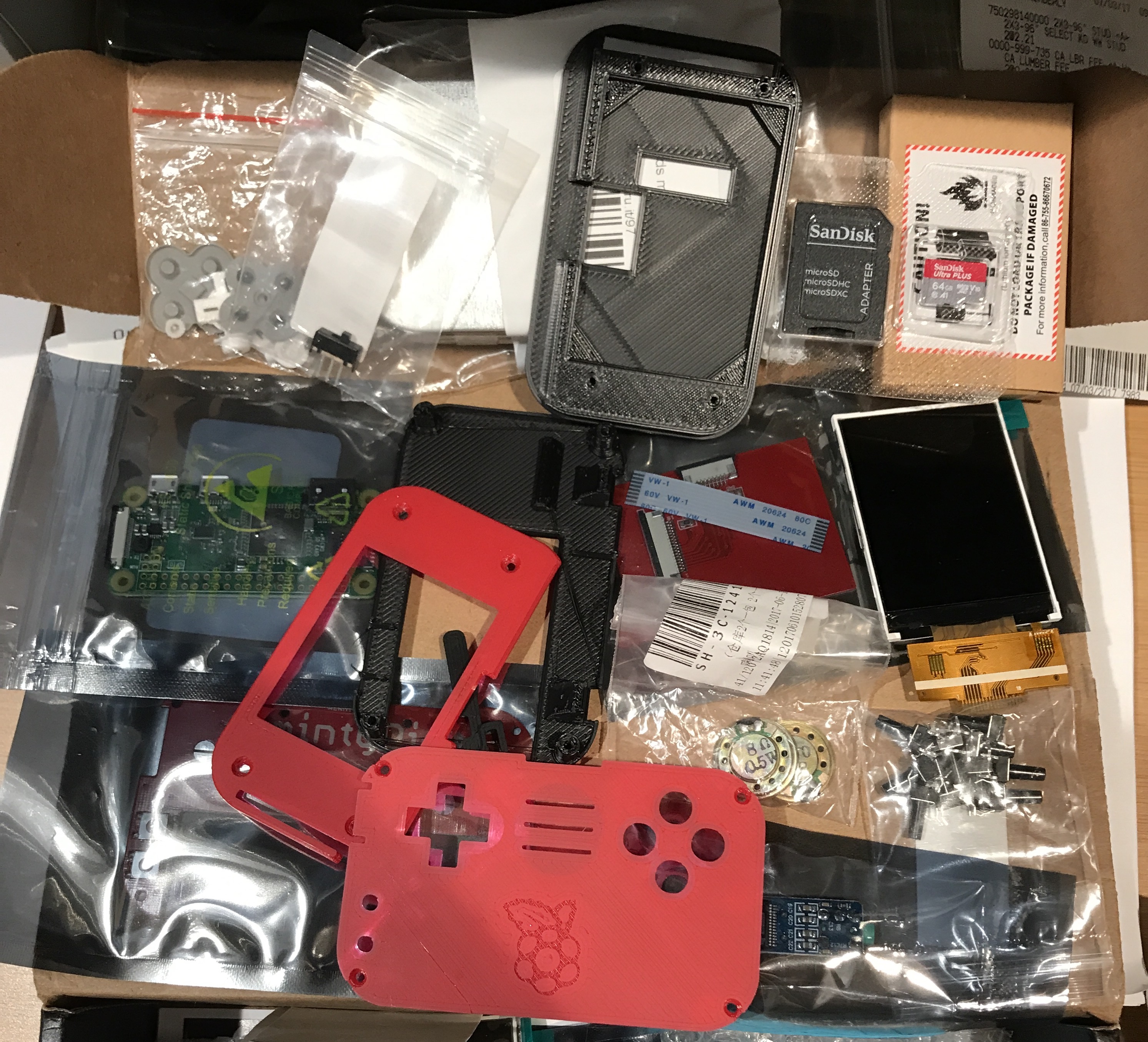
- IMG_0688.JPG (1.79 MiB) Viewed 8656 times
That's all for now and likely all I'll get to until after SDCC17.
Re: [WIP] MintyPi build from ClonemyPi
Posted: Tue Jul 18, 2017 3:23 pm
by exodus
Mod team, can we please move this topic to mintypi show off corner? thanks
Re: [WIP] MintyPi build from ClonemyPi
Posted: Tue Jul 18, 2017 3:30 pm
by HoolyHoo
Done

Re: [WIP] MintyPi build from exodus
Posted: Sat Aug 26, 2017 5:26 pm
by exodus
Back at it after waiting for parts and tools. Sound card successfully disassembled
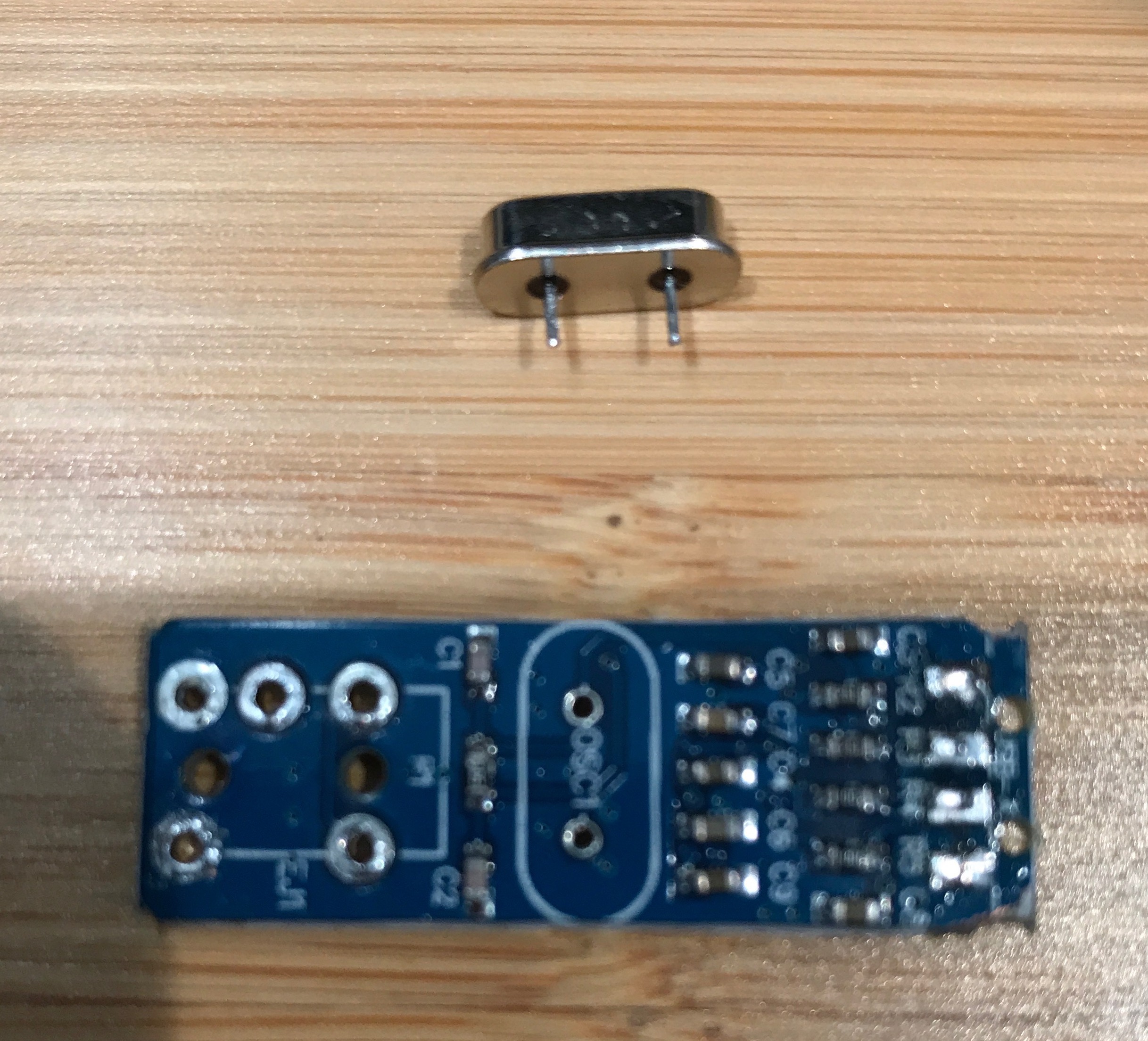
- soundcard.jpg (1010.12 KiB) Viewed 8155 times
Re: [WIP] MintyPi build from exodus
Posted: Mon Aug 28, 2017 7:27 pm
by Lphillimore
Nice work!
Re: [WIP] MintyPi build from exodus
Posted: Sun Oct 22, 2017 5:35 pm
by exodus
Hi,
Long time no post

Terrible how life gets in the way of projects. However, last night I able to put some work in!
I was working on through hole soldering my Pi Zero to the PCB board. I wasn't have much luck with validating good contacts with my multimeter. For reference I'm using a Weller WESD51 iron and pen with their small/smallest tip 1/32 ETO or 0.01 ETS. I'm also using Kester "245" 63/37 0.015" diameter solder. My method was drip some solder into the hole and then push the tip in to drive it done and keep repeating. I believe I had one solid contact. After some frustration, I decided to game and unscrew the Pi to see if any solid connections were made. To my surprise the PI lifted off clean! So I was never making any real contact.
So, comments please, what am I not doing correctly? Pics for reference of the boards. Thanks team!
Re: [WIP] MintyPi build from exodus
Posted: Sun Oct 22, 2017 5:51 pm
by dryja123
What temp are you soldering at? I use the same station and the same tip at 600f. You should drip solder into the hole you should feed the solder into the hole. Once you have solder in the hole stick the tip in (giggidy) leave it there for a second, wiggle, and pull out. Flux helps too.
Re: [WIP] MintyPi build from exodus
Posted: Sun Oct 22, 2017 9:58 pm
by exodus
Thanks. The increased temperature worked well. Appreciate the suggestion. I was able to connect up a PCB and pi easily this evening! Thanks @dryja123
Re: [WIP] MintyPi build from exodus
Posted: Sun Oct 29, 2017 4:59 pm
by exodus
Hi, made a bunch of progress over the last two evenings. I also encountered a problem that I was able to debug. Sorry for the lack of pics, I just kept working.
I had finishing soldering the PiW to the PCB and was attempting to test the screen. Initially the cable wouldn't sit in place. I realized I had one too many layers of tape that was preventing the cable for sitting deep enough for the latch to catch it. On my first power up I was receiving a partial white screen but it flickered on and off. I removed the ribbon cable and spent a bit of time really focusing on aligning the pins. That did the trick, the screen successfully powered on, and I was able to use the membranes to navigate and power down the Pi via emulation station.
So, I will stress to anyone having screen issues, to pay attention to the ribbon cable placement. This really only applies to Helder screen 1.0 as the newest version is already attached.
Progress: Sound card all wired up. Wired up the speaker and power supply and switch. Test fitted the buttons and shaved the 3D parts as needed.
Next to do: wire up battery to power and switch and install. Install buttons, screw down PCB, add screen, screen down 3D part. Test again