Page 1 of 1
Non functional screen help
Posted: Tue Apr 11, 2017 7:48 pm
by surprisesushi
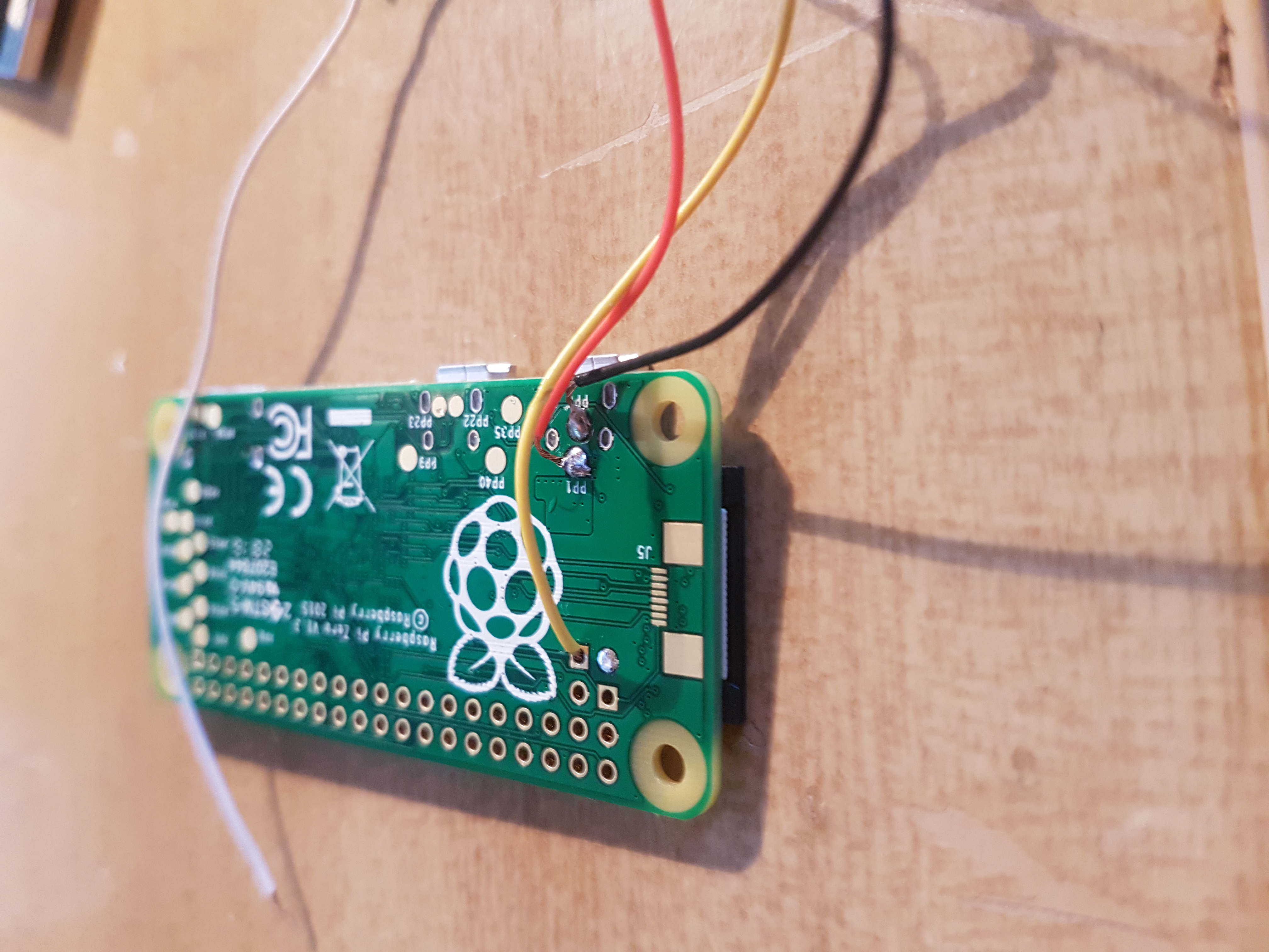
Just throwing together some parts, but my screen isn't doing anything. I believe I have it all hooked up right? Any help would be appreciated!!

- 20170411_184019.jpg (3.56 MiB) Viewed 5389 times
- 20170411_184207.jpg (3.15 MiB) Viewed 5389 times
Re: Non functional screen help
Posted: Wed Apr 12, 2017 8:06 am
by jostie94
connect the yellow wire to the other video input (the round-shaped )
Re: Non functional screen help
Posted: Wed Apr 12, 2017 8:15 am
by rodocop
jostie94 wrote: ↑Wed Apr 12, 2017 8:06 am
connect the yellow wire to the other video input (the round-shaped )
The Square pin is the video pin, the round one beside it is ground, connecting the yellow cable to that pin will do nothing. Keep the yellow wire in the square tv hole. Or try to use the white wire in the tv hole, yellow and white are likely input 1 and 2.
Did the display work before you connected it to the pi? Did you test it with 12v before you did the 5v mod? Maybe post a better picture of the mod you did for 5v, I can't see exactly where the red wire goes to and how well it is soldered. Maybe you have a bad solder joint, or you have it soldered to the wrong place for a 5v mod.
Also, this might be obvious, but make sure the pi is plugged in and you have a SD card with a proper image in the pi to get a display, do you have your SD card in there?
Re: Non functional screen help
Posted: Wed Apr 12, 2017 1:30 pm
by Kalei808
You can test that you have a proper image on the sd card and that the pi boots up with a hdmi cord hooked up to a tv. as rodocop said, the square hole is the tv out. Use either the yellow or white wire only to connect to the tv out.
Re: Non functional screen help
Posted: Sat Apr 15, 2017 11:19 am
by surprisesushi
rodocop wrote: ↑Wed Apr 12, 2017 8:15 am
jostie94 wrote: ↑Wed Apr 12, 2017 8:06 am
connect the yellow wire to the other video input (the round-shaped )
The Square pin is the video pin, the round one beside it is ground, connecting the yellow cable to that pin will do nothing. Keep the yellow wire in the square tv hole. Or try to use the white wire in the tv hole, yellow and white are likely input 1 and 2.
Did the display work before you connected it to the pi? Did you test it with 12v before you did the 5v mod? Maybe post a better picture of the mod you did for 5v, I can't see exactly where the red wire goes to and how well it is soldered. Maybe you have a bad solder joint, or you have it soldered to the wrong place for a 5v mod.
Also, this might be obvious, but make sure the pi is plugged in and you have a SD card with a proper image in the pi to get a display, do you have your SD card in there?
Yes, the display did work when I tested it before, so I'll try switching wires from yellow to white and touch up the 5V mod. I'm still not the best at soldering, so it very well could be that. Thanks! I'll give it a shot, and if it doesn't work I'll take some better pics and upload. Thank you!