Page 1 of 2
Screen help for 5v
Posted: Thu Jun 16, 2016 3:26 am
by 401Gaming
So I just picked up this screen off of eBay and need help wiring it up for 5v. Has anyone else used this screen? What needs to be done
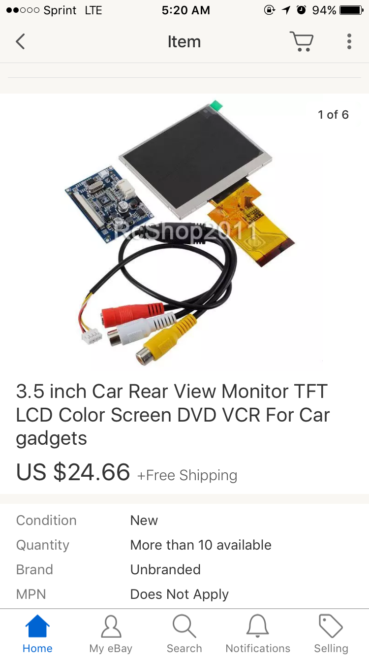
- image.png (338.94 KiB) Viewed 11131 times
Re: Screen help for 5v
Posted: Thu Jun 16, 2016 3:53 am
by Fleder
A better picture of the board would be helpful.
I can't tell for sure but is looks like this one:
http://sudomod.com/wiki/index.php?title ... te_Display
We have a wiki, where you can read about those things.
To be sure you would have to post a better picture of the display board.
Re: Screen help for 5v
Posted: Thu Jun 16, 2016 5:21 am
by 401Gaming
Fleder wrote:A better picture of the board would be helpful.
I can't tell for sure but is looks like this one:
http://sudomod.com/wiki/index.php?title ... te_Display
We have a wiki, where you can read about those things.
To be sure you would have to post a better picture of the display board.
It is slightly different than that one. I checked the wiki first to be sure. I'll snap a picture of mine when I get home for work today and post it so you guys can get a better look
Re: Screen help for 5v
Posted: Thu Jun 16, 2016 4:18 pm
by 401Gaming
Fleder wrote:A better picture of the board would be helpful.
I can't tell for sure but is looks like this one:
http://sudomod.com/wiki/index.php?title ... te_Display
We have a wiki, where you can read about those things.
To be sure you would have to post a better picture of the display board.
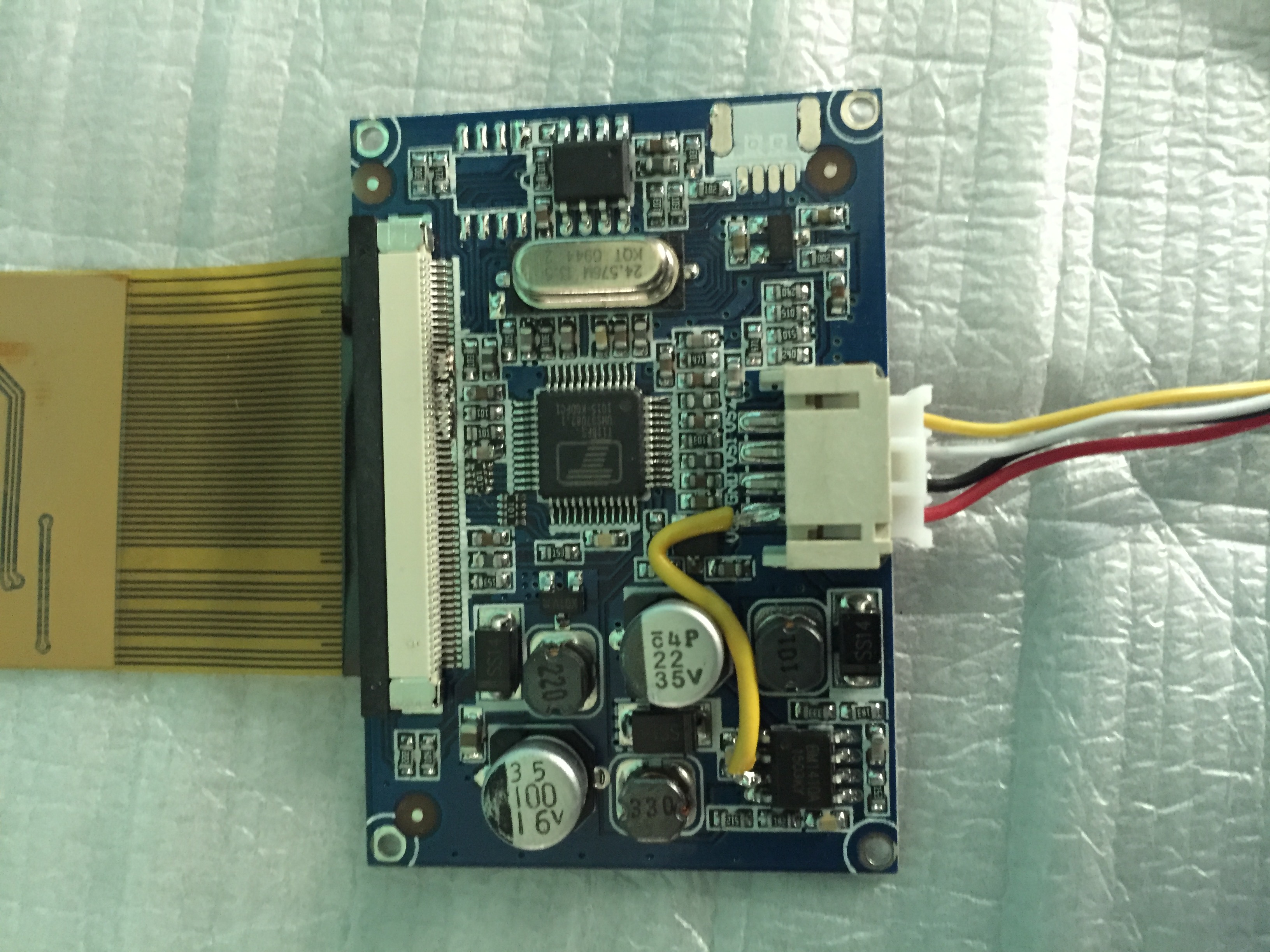
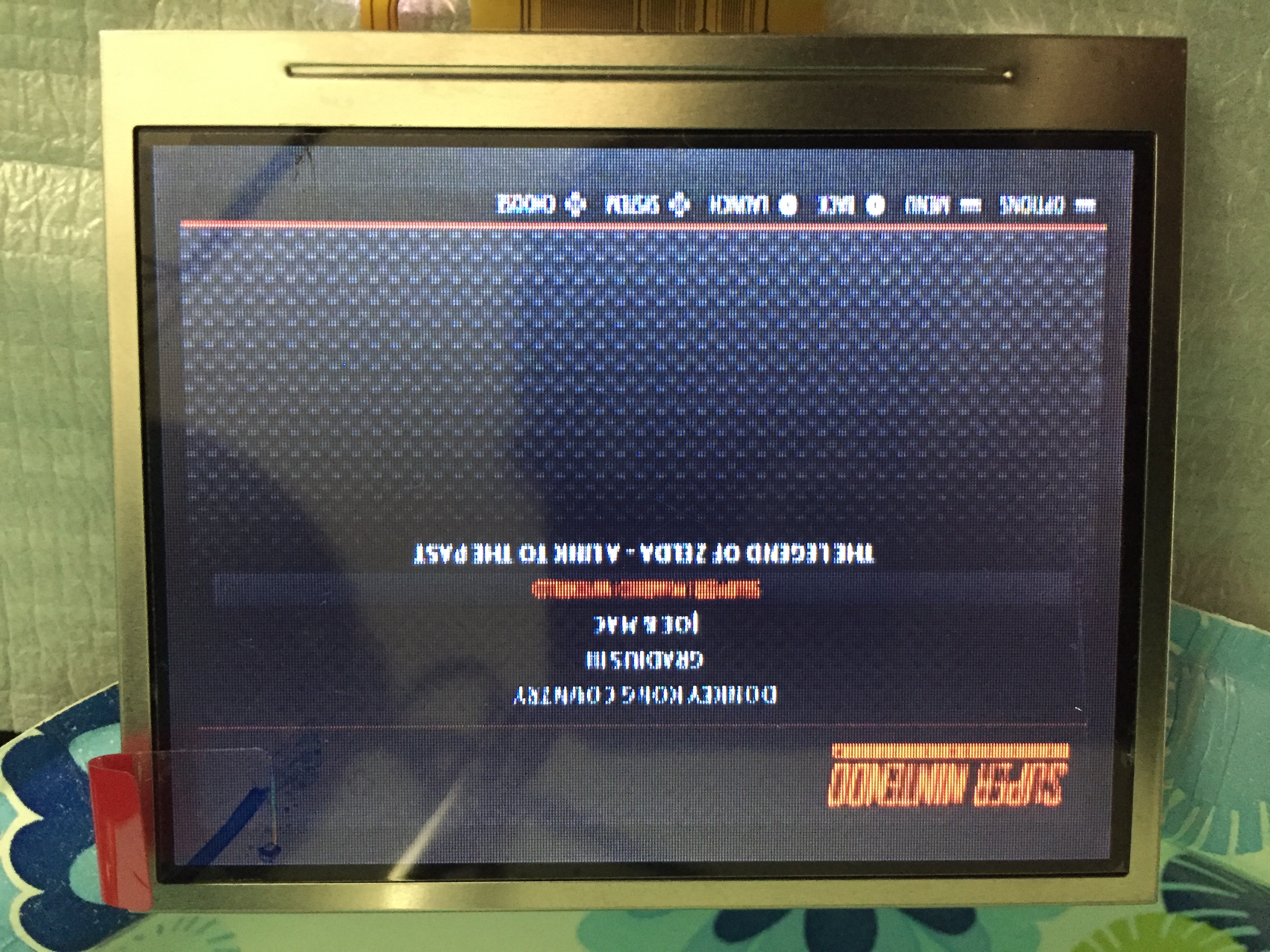
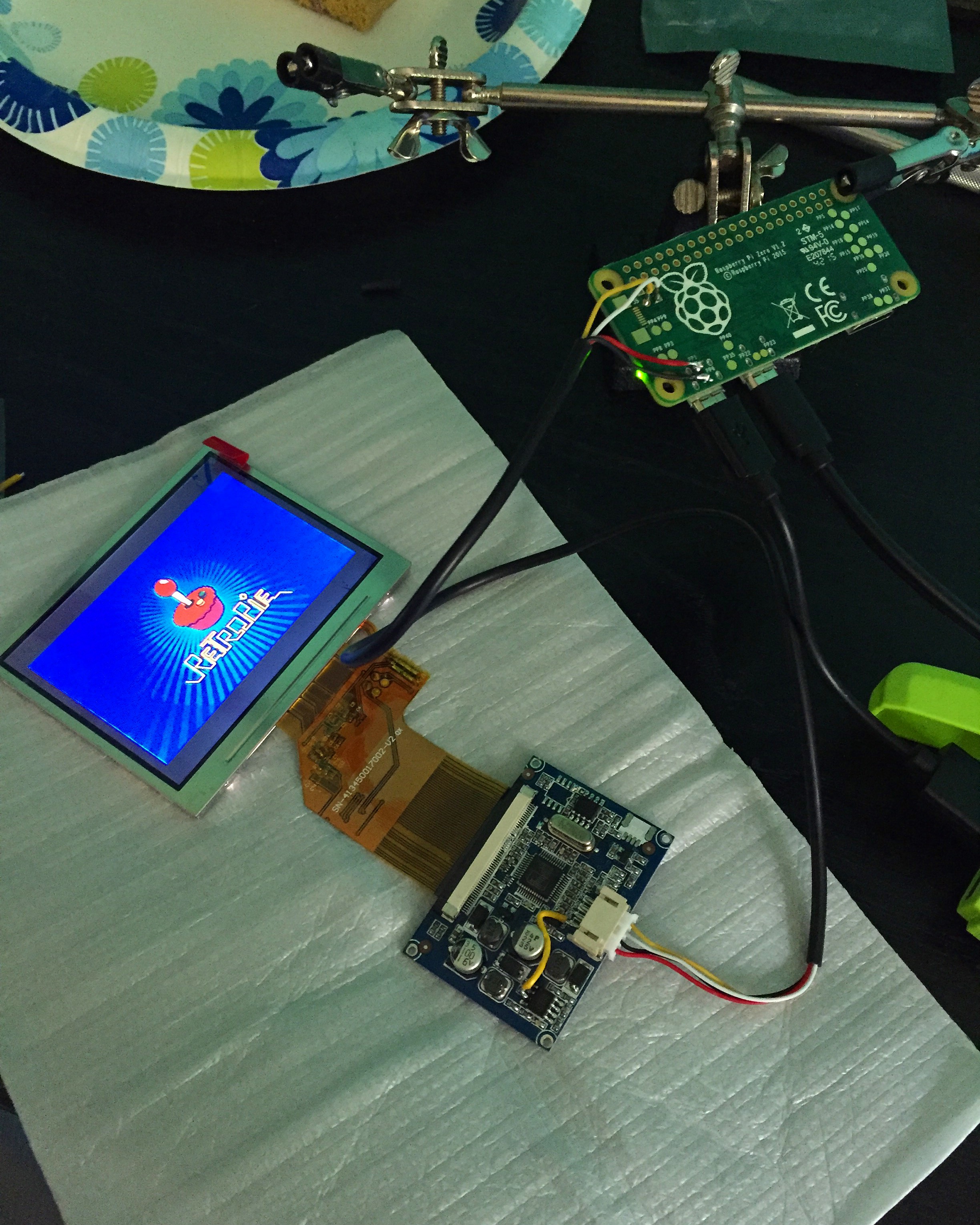
Ok so I got home and tinkered with it a little and got it running off 5v. But there seems to be some noise in the display and some words are tough to make out. Is this error on my part? Or just the screen itself
- image.jpeg (1.34 MiB) Viewed 11072 times
- image.jpeg (2.22 MiB) Viewed 11072 times
- image.jpeg (1.52 MiB) Viewed 11072 times
Re: Screen help for 5v
Posted: Thu Jun 16, 2016 11:06 pm
by Robvp
I think the "noise" is normal, the screen res is 320x240, mine looks similar
Re: Screen help for 5v
Posted: Fri Jun 17, 2016 1:08 am
by Fleder
The noise could be a side effect of the 5v.
Either it really needs more or you have to desolder a IC to make it better. But yes, it could also be the display.
If you want to tinker a bit more, desolder the IC you just soldered the wire onto.
But be careful, so you might be able to reattach it, if it does not work.
This COULD get rid of the "noise".
The bad resolution, well, it's 320x240 px. No surprise the words are not that easy to read.
Re: Screen help for 5v
Posted: Sat Jun 18, 2016 2:44 am
by zpnq
Hello,
What makes you suggest removing the IC it is connected to?
I have this monitor and may try what you suggest with a little more explanation.
Regards.
Re: Screen help for 5v
Posted: Sat Jun 18, 2016 2:22 pm
by FreddySalted
401Gaming wrote:
Ok so I got home and tinkered with it a little and got it running off 5v. But there seems to be some noise in the display and some words are tough to make out. Is this error on my part? Or just the screen itself
I've got the same screen, Try cutting the Yellow wire, it looks like you've doubled up the video input and wired the second one (Yellow) directly to ground. If that doesn't work try swapping the yellow wire to the white wires location on the RPi
The white PCB connector shares a common ground between all the plugs and i'm guessing that the white and yellow jacks are for 2 separate video signals
Re: Screen help for 5v
Posted: Sun Jun 19, 2016 7:44 am
by Mischief
I have purchased the same one
http://r.ebay.com/3K0mtn I assumed the white and yellow wires were separate inputs so the ground of the video signal had to be put on the ground (black) wire?
I may be completely wrong but at least I now know it needs modding for 5V

Re: Screen help for 5v
Posted: Mon Jun 20, 2016 5:37 am
by Mischief
Mine turned up today and I did the 5V mod and tested I get the fuzzy image the same as yours but I did open up the centre part of the loom and found that the black wire is a common ground for all 3 plugs.
[spoiler="image"]

[/spoiler]
I am planning on removing the IC [mention]Fleder[/mention] mentioned in the above post and will test it and see how that works.