I'm new at the forums and this is going to be my first post, so first of all, hello everyone!
I have an old Game Boy Color lying arround, but sadly it doesn't work, so I want to make a Game Boy Color Zero with the raspberry that I have.
Unfortunately, I couldn't find any AIO board for the Color version, so I have to do my own.
It's based in the post: https://www.sudomod.com/forum/viewtopic.php?f=42&t=6499
I ended up with something like this
PicsShow
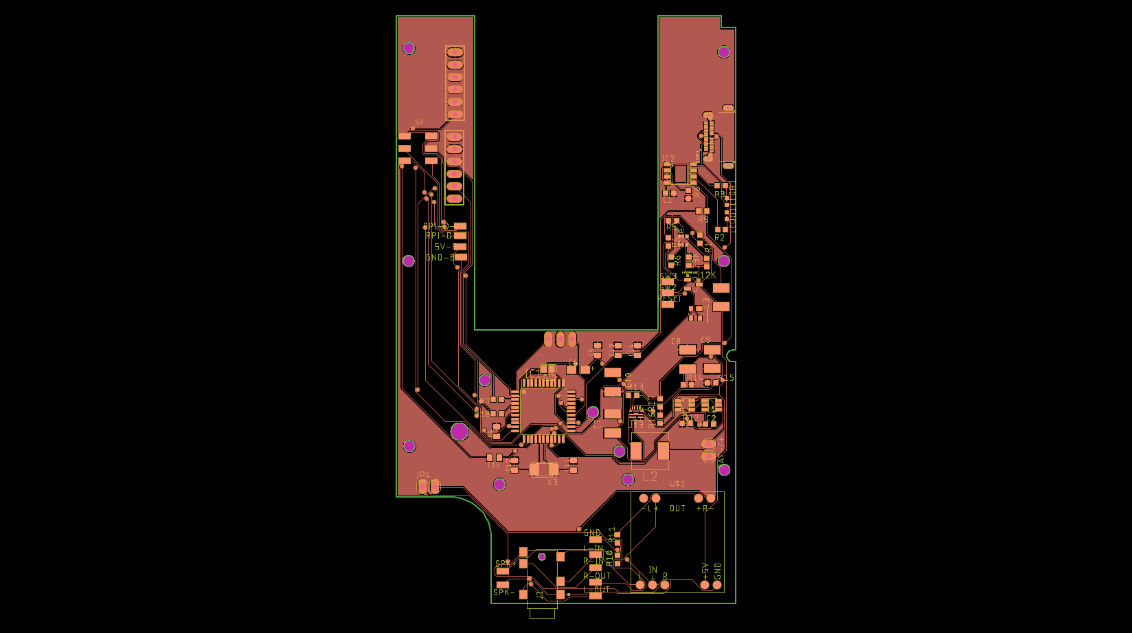
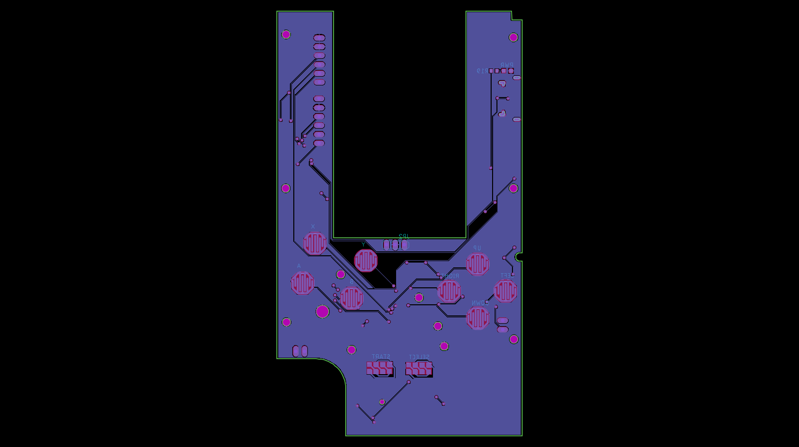
ChangesShow
- Added L/R buttons
- Added a programming and a bootloader connectors to burn the bootloader or programm the ATMEGA chip
TODOShow
- Change the battery protection circuit to allow for 2 1.5V batteries, so they can be put in the battery holder of the GBC
- Change the audio amp board for an in-board design
- On-screen battery indicator based on https://learn.adafruit.com/adafruit-ina ... e?view=all
- Support for a screen
So, thats all! I left my board and schematic (schematic is almost the same that the rlcmtzc12's post) so anyone can see/modify the design.
https://github.com/miguellahoz/Game-Boy-Color-AIO
Thank you all!
Edit 1:
So, I changed how I can do some things, so first of all I'm going to post here all the circuits that I have my board to have, what IC's I want to use and, when I have it designed, the schematics.
Also, I'm going to change the input system, so it uses the GPIO pins of the Raspberry instead of the USB port.
And I also added a folder in the github with the PCB design empty with the screws holes for the GBC.
Battery Protection CircuitShow
I'm planning to use a Li-Po battery, I was thinking about this one: http://www.crazell.com/product/703048/.
This batteries usually comes with their own protection circuit, so I don't need one in the board.
This batteries usually comes with their own protection circuit, so I don't need one in the board.
Boost circuit (Step up/down)Show
We have a battery that could give 4.2V to 3.7V, we need to boost this voltage to 5V.
The best IC that I could find is the TPS61240.
Data and datasheet: http://www.ti.com/product/tps61240
The best IC that I could find is the TPS61240.
Data and datasheet: http://www.ti.com/product/tps61240
Charging circuitShow
Actually, I'm using a circuit based in the TC4056A, and it works fine, so I'm looking for another ICs, but this one seems fine.
WIP
WIP
ShutDown CircuitShow
A circuit that shuts down the Rapsberry when low battery is detected. It could be done with a detector IC, with the boost circuit (for some ICs), or with programming if it's a software battery level indicator
AudioShow
I need a circuit that can amplify audio, and turn off the speaker when a headphone is detected.
ScreenShow
I'm still looking for a screen that fits, the maximum size is arround 55.8 x 57 mm, maybe a little more if we don't keep the power indicator in the screen, it becomes 56 x 65.8 mm.
