
Ah, that's what is called -- diffuser! I can't recall the word when I posted yesterday. Sure, you can "borrow" the idea. That's the point of us sharing in the forums anyway!
chiz's GB Pi2
Re: chiz's GB Pi2
Thanks, man! 
Ah, that's what is called -- diffuser! I can't recall the word when I posted yesterday. Sure, you can "borrow" the idea. That's the point of us sharing in the forums anyway!
Ah, that's what is called -- diffuser! I can't recall the word when I posted yesterday. Sure, you can "borrow" the idea. That's the point of us sharing in the forums anyway!
-
dirtybeagles

- Posts: 386
- Joined: Thu May 05, 2016 6:04 am
- Has thanked: 34 times
- Been thanked: 64 times
-
dirtybeagles
- Posts: 386
- Joined: Thu May 05, 2016 6:04 am
- Has thanked: 34 times
- Been thanked: 64 times
Re: chiz's GB Pi2
Hey Chiz, I see you went with USB audio and I have no problems with that at all. Curious though on if you ever found a way to connect audio directly to the pi2 from your diagram?
- 2016-06-17 10_57_30-chiz's GB Pi2 - sudomod.png (295.69 KiB) Viewed 9046 times
Re: chiz's GB Pi2
Here are some from Amazon:dboSS wrote:Can you share the link to that power bank?chiz wrote:I used the 2500mah lipo from the power bank which fits in the battery bay.
1. GYMLE branded
2. Kolumb branded
@dirtybeagles
I didn't try since I'm already getting audio from the USB DAC.I documented the pinout though for reference before I removed the stereo jack just in case I needed to get audio from the jack.
Re: chiz's GB Pi2
*** Update #16 ***
Today, I was able to complete soldering the USB DAC, Teensy and audio using original pot and 3.5 jack.
I was looking for the best spot to put the Teensy that will minimize the amount of visible wires. I thought where could it be but parallel to the controller PCBs traces! Instead of soldering the wires straight through the trace holes, I decided to solder the wires on the surface, with the soldered wires forming a "U". This way, I can still lift the Teensy as I test it, making the soldered wires acting as a hinge. [spoiler="Completed wiring the Teensy, USB DAC, and audio"]
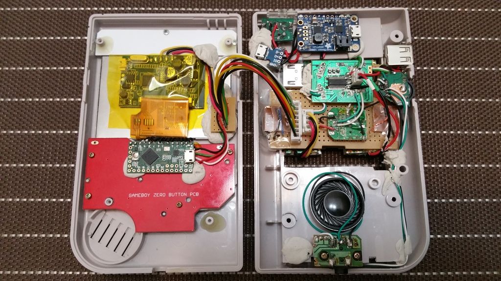 [/spoiler][spoiler="Testing for boot..."]
 [/spoiler]
Also did some test fitting...[spoiler="Test fitting - side view"] [/spoiler][spoiler="Test fitting - top view"]
 [/spoiler][spoiler="Test fitting - showing location of Teensy and JST connector"]
 [/spoiler]
One of the reasons why I placed the PowerBoost at the top behind the screen is to minimize additional work for seeing the PowerBoost indicators LEDs. Instead of boring another hole for the PowerBoost blue LED power indicator, I thought of using a clear power button and hope that the blue LED will shine through. Turns out it's bright! Picture below shows the Kitsch-Bent clear power button against the PowerBoost blue LED. [spoiler="Effect of Kitch-Bent clear power button against the PowerBoost 1000C power LED"] [/spoiler]
Just a few more work to do wiring the LCD remote and battery connector.
Today, I was able to complete soldering the USB DAC, Teensy and audio using original pot and 3.5 jack.
I was looking for the best spot to put the Teensy that will minimize the amount of visible wires. I thought where could it be but parallel to the controller PCBs traces! Instead of soldering the wires straight through the trace holes, I decided to solder the wires on the surface, with the soldered wires forming a "U". This way, I can still lift the Teensy as I test it, making the soldered wires acting as a hinge.
[/spoiler][spoiler="Testing for boot..."][/spoiler]Also did some test fitting...[spoiler="Test fitting - side view"]
[/spoiler][spoiler="Test fitting - top view"][/spoiler][spoiler="Test fitting - showing location of Teensy and JST connector"][/spoiler]One of the reasons why I placed the PowerBoost at the top behind the screen is to minimize additional work for seeing the PowerBoost indicators LEDs. Instead of boring another hole for the PowerBoost blue LED power indicator, I thought of using a clear power button and hope that the blue LED will shine through. Turns out it's bright! Picture below shows the Kitsch-Bent clear power button against the PowerBoost blue LED. [spoiler="Effect of Kitch-Bent clear power button against the PowerBoost 1000C power LED"]
[/spoiler]Just a few more work to do wiring the LCD remote and battery connector.
Last edited by chiz on Sun Jun 19, 2016 5:19 am, edited 1 time in total.
-
Aiolia33Fr

- Posts: 30
- Joined: Tue May 10, 2016 12:35 am
- Has thanked: 8 times
- Been thanked: 5 times
-
dirtybeagles
- Posts: 386
- Joined: Thu May 05, 2016 6:04 am
- Has thanked: 34 times
- Been thanked: 64 times
Re: chiz's GB Pi2
Hey Chiz, another question for you... if you do not mind.
Why use a USB hub for the PI2? I think the PI2 has four USB inputs so I was going to solder the USB Audio and the other spare USB ports directly to the PI2. Thoughts?
Why use a USB hub for the PI2? I think the PI2 has four USB inputs so I was going to solder the USB Audio and the other spare USB ports directly to the PI2. Thoughts?
Re: chiz's GB Pi2
@dirtybeagles
For upgrade reasons. I want to minimize the amount of soldering to the RPi so that anytime I upgrade it, I only solder the following:
1. +5V power input
2. GND
3. Video out
4. USB D+
5. USB D-
If I use the Pi's built-in hub, I will have to solder at least 4 more connections.
For upgrade reasons. I want to minimize the amount of soldering to the RPi so that anytime I upgrade it, I only solder the following:
1. +5V power input
2. GND
3. Video out
4. USB D+
5. USB D-
If I use the Pi's built-in hub, I will have to solder at least 4 more connections.
Who is online
Users browsing this forum: No registered users and 1 guest