Page 1 of 1
daddelkischde AIO PCB
Posted: Thu May 17, 2018 2:34 pm
by floppes
Today I'd like to show you my first Game Boy Zero which I built with a PCB my friend Chris designed (and I reviewed): daddelkischde. The name is German in a southern dialect and not easy to translate. "Play box" could fit

When Chris showed me some Game Boy Zeros last October on the net, I was hooked right away. But we both didn't like the many components glued into the case and it was hard to get Kite's AIO, so we decided to create our own PCB. v0.1 did not work, but v0.2 is here and it works perfectly

The features:
- buttons are connected to shift registers, behave like an SNES controller (driver: gamecon_gpio_rpi) and use only three pins on the Pi
- PCB and STL for shoulder buttons with conductive pads
- LiPo charger and boost converter (same ICs as on Adafruit PowerBooost 1000 Charger), charge and play simultaneously
- micro USB port for charging
- solder pads for LEDs: charging, charging finished, low battery
- stereo poti to control volume
- stereo headphone jack
- mono amplifier for speaker
- ADC to measure battery voltage (Python script available to display battery icon on display)
- 2-port USB hub (one free internal port, one external USB A port)
- optimized for HDMI display
If there is demand, we could produce a batch for about 50 € + shipping per piece.

- Front
- 1.jpg (50.68 KiB) Viewed 8334 times

- Back (yeah, I messed up the drilling, the buttons are not in line :/ )
- 2.jpg (69.09 KiB) Viewed 8334 times

- Volume control on the left side
- 3.jpg (36.38 KiB) Viewed 8334 times
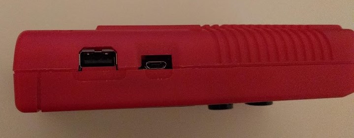
- USB A port for external devices, micro USB port for charging on the right side
- 4.jpg (39.15 KiB) Viewed 8334 times

- Inside, during assembly
- 5.jpg (267.99 KiB) Viewed 8334 times
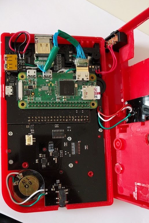
- Almost fully assembled, except for the dummy cartridge with LEDs
- 6.jpg (116.9 KiB) Viewed 8334 times

- PCB top
- 7.jpg (56.21 KiB) Viewed 8334 times
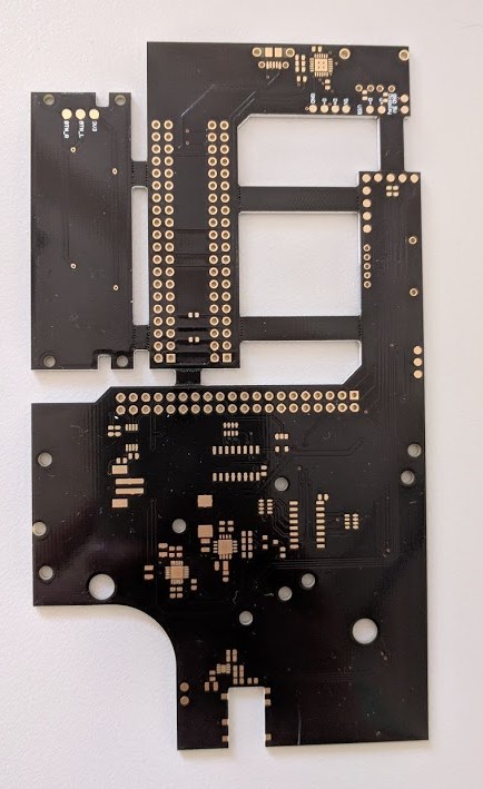
- PCB bottom
- 8.jpg (69.01 KiB) Viewed 8334 times
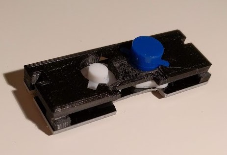
- Shoulder buttons
- 9.jpg (21.29 KiB) Viewed 8334 times
Re: daddelkischde AIO PCB
Posted: Thu May 17, 2018 9:37 pm
by VeteranGamer
Really nice (you friend did really good)...
Also good to see a HDMI screen being used....
At around €40, you will definitely see demand....
Good luck if you do decide to list these in the For Sale section of this forum...
.
Re: daddelkischde AIO PCB
Posted: Thu May 17, 2018 9:49 pm
by rodocop
Nice looking board. I'm sure you will have some interest.
Few things:
Personal preference. But I prefer the shoulder buttons to be farther apart. These seem pretty close.
It would also be nice to have access to the sd card from the contrast slot. I understand why it is not though. And it is not necessary.
Have you guys considered using a barrel jack for charging to fit the original dc port, and then volume wheel where the microusb is and sd in the contrast?
Just me being picky. But overall it looks very nice. I'd consider buying one.
Re: daddelkischde AIO PCB
Posted: Fri May 18, 2018 1:17 am
by floppes
Thanks for your feedback!
I just noted that I had a typo in the estimated price, it's 50 €, not 40.
@rodocop
We experimented with the position of the shoulder buttons. I had them even closer together on my first case (the black one):
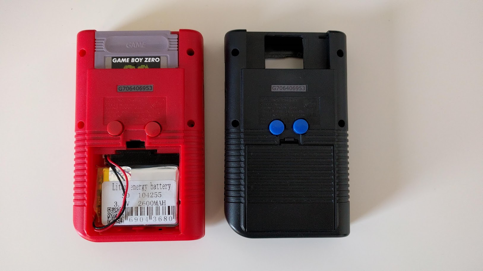
- 1.jpg (197.93 KiB) Viewed 8262 times
The closeup photo in my first post of the shoulder button PCB shows the one for the black case.
We will stretch the pads on the PCB to be flexible with the position of the conductive pads. The 3D printed part will then determine the actual position of the buttons and I can make different versions of the STL.
We thought about the SD card but decided it's not necessary and would be another ~1,50 € on the bill. If someone wants to have access to it, he has to build it by himself. It could be put into the dummy cartridge or somewhere at the bottom.
We wanted micro USB for charging as most people (including ourselves) have spare USB chargers from old phones at home. I think we will stay withe the current layout, it took enough time to get all components perfectly arranged

Re: daddelkischde AIO PCB
Posted: Fri May 18, 2018 5:13 am
by ekilla
I like it. I would buy one.
Btw. since you soldered your HDMI cable yourself, if you take a 90° HDMI plug or a very short standard one on the full size end, you could get rid of the HDMI Adapter that came with the display. Than you can plug your cable directly into the display and you should be able to leave the cartridge slot as it is, without cutting the whole thing away.
Re: daddelkischde AIO PCB
Posted: Sun May 20, 2018 3:22 am
by Tas262
I'd definitely be interested if you put these into production.
Re: daddelkischde AIO PCB
Posted: Tue May 22, 2018 11:57 am
by rodocop
floppes wrote: ↑Fri May 18, 2018 1:17 am
Thanks for your feedback!
I just noted that I had a typo in the estimated price, it's 50 €, not 40.
@rodocop
We experimented with the position of the shoulder buttons. I had them even closer together on my first case (the black one):
1.jpg
The closeup photo in my first post of the shoulder button PCB shows the one for the black case.
We will stretch the pads on the PCB to be flexible with the position of the conductive pads. The 3D printed part will then determine the actual position of the buttons and I can make different versions of the STL.
We thought about the SD card but decided it's not necessary and would be another ~1,50 € on the bill. If someone wants to have access to it, he has to build it by himself. It could be put into the dummy cartridge or somewhere at the bottom.
We wanted micro USB for charging as most people (including ourselves) have spare USB chargers from old phones at home. I think we will stay withe the current layout, it took enough time to get all components perfectly arranged

Totally makes sense. I don't expect you to make changes! If i built one using this PCB I would just place an LED for charging status in the DC port to not leave it empty. I agree that micro USB in more convenient. Since people usually have so many of those cords laying around!
And yeah, for the shoulder buttons it's all personal preference. And if there is a bit or wiggle room, people can place them wherever they want.
Re: daddelkischde AIO PCB
Posted: Wed May 23, 2018 1:27 pm
by floppes
@ekilla
You're right, I could have used another HDMI plug. But we had the flat ones here already so I used one of them

If they run out I will switch to the 90° version.
@rodocop
One could use an RGB LED in the DC port and display all three states with it. There are never two or more LEDs on at the same time, just one or none. Maybe for my next build...

Here are two pictures with the LEDs inside the cartridge:

- IMG_20180523_204346.jpg (48.95 KiB) Viewed 7935 times

- IMG_20180522_205317.jpg (97.76 KiB) Viewed 7935 times
Re: daddelkischde AIO PCB
Posted: Thu May 31, 2018 5:06 am
by spacemishka
Ich würde mich auch dafür interessieren

.
Grüße aus dem Norden

