Hey I searched the fourms and can't find my answer so I apologise if it has already been covered.
I am using the 2 tactile switches for L&R as the guides show but I can't figure out how to wire them.
When I put my meter on the switch pins each side has continuity, but top and bottom are open (I know my pin description is relative). When the switch is closed everything has continuity. That being said I saw that you can tie the grounds together on the switches, but does it matter what pins on the switches go to the GPIOs? I am assuming just pick two pins tie them together and use the opposite side of the switch to go to the GPIOs for each button? As I typed this I am thinking that I am over thinking this but I figured it wouldn't hurt to ask.
Thanks in advance for your assistance!
Tactile Switch Wiring?
Re: Tactile Switch Wiring?
Could you post a picture and which type of board your using for your build?..I ask because some boards have solder points designated for the back buttons. Without knowing what were looking at, it's a shot in the dark
Some of these guys sell L1 L2 R1 R2 switch boards. I know HoolyHoo had some in the Sale section of the board, and Kite sends one with the Circuit Sword purchase.
Here's mine


Some of these guys sell L1 L2 R1 R2 switch boards. I know HoolyHoo had some in the Sale section of the board, and Kite sends one with the Circuit Sword purchase.
Here's mine
-
sonarsup1934
- Posts: 4
- Joined: Sun Oct 28, 2018 6:41 pm
Re: Tactile Switch Wiring?
Looks identical to this setup from Wermy. Wiring straight into the GPIO because my board doesn't have a LR built onboard.
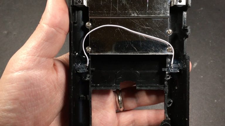
Pic of my board

Pic of my board
Re: Tactile Switch Wiring?
It looks like your using Wermy's method, which requires a few extra steps than the newer boards. If I'm not mistaken, you should be able to connect the L and R buttons to the Teensy. From what I've seen/read, they would go to pins 10 and 11. I noticed there are Ground (GND) pins on each side of the board but nothing else, that is where they are in the updated boards (L1/L2/GND) on one side and (R1/R2/GND) on the other side.
Anyway, if you can figure it out, you can use a Teensy to connect your L1/L2 and R1/R2.
Anyway, if you can figure it out, you can use a Teensy to connect your L1/L2 and R1/R2.
Who is online
Users browsing this forum: No registered users and 1 guest