Page 1 of 1
Screen Help please!
Posted: Thu Nov 09, 2017 2:47 am
by RAYDEO
HI team, I finally picked up one of these screens for my project, but i cant seem to get any life out of it... can someone point me to where i need to stick my 5v?


Im also using a Raspberry Pi3B, as there are no Zeros available in New Zealand, i used this guide -
https://pinout.xyz/pinout/ground
Does this seem accurate? or do i need to run some code to activate these pins?
Re: Screen Help please!
Posted: Thu Nov 09, 2017 3:06 am
by VeteranGamer
RAYDEO wrote: ↑Thu Nov 09, 2017 2:47 am
HI team, I finally picked up one of these screens for my project, but i cant seem to get any life out of it... can someone point me to where i need to stick my 5v?
Im also using a Raspberry Pi3B, as there are no Zeros available in New Zealand, i used this guide -
https://pinout.xyz/pinout/ground
Does this seem accurate? or do i need to run some code to activate these pins?
i'm not 100% if this is the back of a Pi3, but it may be of some help (it should point you in the right direction)....

you'll find a list of the test pad here:
http://ozzmaker.com/testing-points-raspberry-pi/
.
Re: Screen Help please!
Posted: Thu Nov 09, 2017 12:36 pm
by RAYDEO
so your saying use the pads instead of the pins?
those seem to correlate with what i have as a pad layout.
thanks!
Still after some help with making the screen fire up on 5v though if anyone has any ideas?
Re: Screen Help please!
Posted: Thu Nov 09, 2017 12:42 pm
by VeteranGamer
RAYDEO wrote: ↑Thu Nov 09, 2017 12:36 pm
so your saying use the pads instead of the pins?
those seem to correlate with what i have as a pad layout.
thanks!
Still after some help with making the screen fire up on 5v though if anyone has any ideas?
the screen looks like a gearbest screen.....
just wire it up and see, i think it should work as it is (no modifications needed)
Try:
5v RED to PP2
GND Black to PP6
Composite Yellow to PP24
Also, even if your board looks slightly different on the back the test points should still be the same
(ie PP24 = composite PP25=audio left PP26=audio right and so on)....
.
Re: Screen Help please!
Posted: Thu Nov 09, 2017 8:32 pm
by tinkerBOY
I have the same lcd board. This one works on 5v-12v without any mod but isuggest you solder the red wire directly to a 5v if you're using a 5v power. Please see picture.
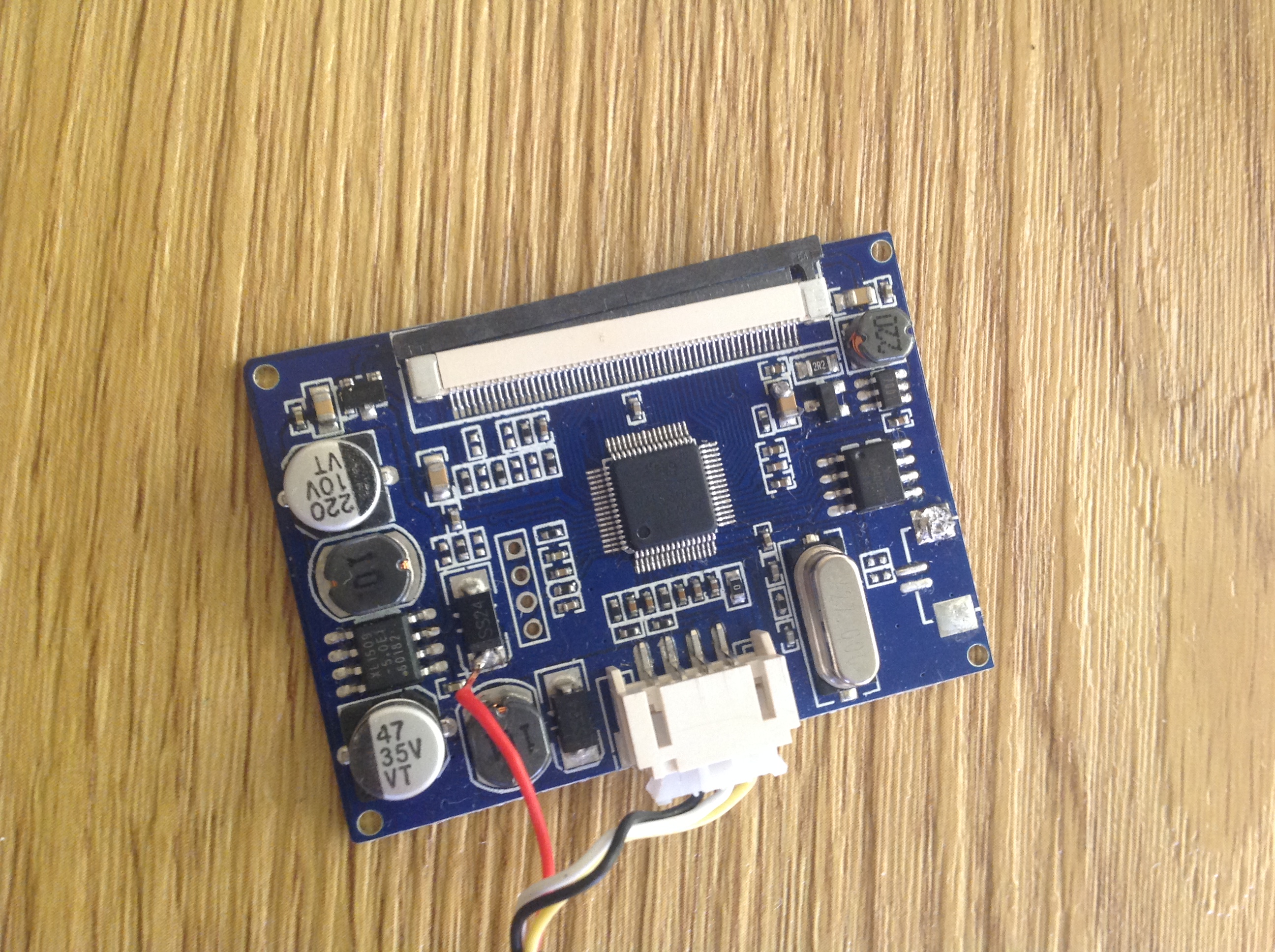
- IMG_1611.JPG (1.83 MiB) Viewed 7418 times
Re: Screen Help please!
Posted: Fri Nov 10, 2017 7:37 pm
by RAYDEO
thanks for the help team,
Got it all together, using a Rpi 3 which isnt the best as theres not much room, Ive ordered a rpi zero from over seas which should arrive in a few weeks.
Also i struggled with wiring the Teency directly to the rpi, so ive left it using a USB cable for now, hence the random cable hanging out the bottom, its together temporarily.

Re: Screen Help please!
Posted: Sat Nov 11, 2017 8:33 am
by rodocop
tinkerBOY wrote: ↑Thu Nov 09, 2017 8:32 pm
I have the same lcd board. This one works on 5v-12v without any mod but isuggest you solder the red wire directly to a 5v if you're using a 5v power. Please see picture. IMG_1611.JPG
I've never done that mod. What purposes does it serve?
Re: Screen Help please!
Posted: Sun Nov 12, 2017 10:27 am
by mike_the_great
That’s Alex Kidd in Miracle World.... you must have had a Master System... one of my favorite games other than the paper rock scissors bosses.