Page 1 of 1

GBZ screen help!

Posted: Sat Feb 16, 2019 10:18 pm
by lord_of_misrule
Hey everyone,

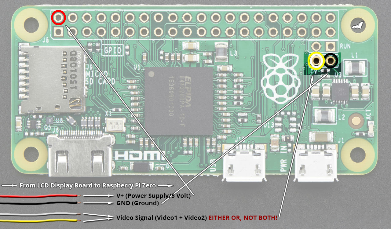
I'm pretty new to the forums and was hoping to handle my problem without having to reach out, but I'm at my wits end! I'm pretty new to the community and decided I wanted to learn soldering and making things. I've made a few projects without an problems, but I've run into snags attempting to build my own Gameboy Zero. Specifically, the screen. I guess I just don't know where the AV1/AV2/Ground/5V goes in regards to my project.

I've plugged both into a mini HDMI up to my monitor and they show working. I have a RetroGamingNow AIO board and the Tinkerboy 3.0.1, respectively.

Tinkerboy:
2.jpeg
2.jpeg (265.72 KiB) Viewed 4563 times
3.jpeg
3.jpeg (305.22 KiB) Viewed 4563 times
1.jpeg
1.jpeg (426.67 KiB) Viewed 4563 times
RGN:
5.jpeg
5.jpeg (444.11 KiB) Viewed 4563 times
8.jpeg
8.jpeg (458.08 KiB) Viewed 4563 times
7.jpeg
7.jpeg (315.04 KiB) Viewed 4563 times
If anyone could point me in the right direction, I'd greatly appreciate it.

-LoM

Re: GBZ screen help!

Posted: Sun Feb 17, 2019 7:39 am
by rodocop
Here is an easy diagram. I always just use the yellow av wire. And cut the white one off.

It shows to power the screen from the pi's gpio too, I always power it from the power strip, not the pi.

https://s20.postimg.cc/8dm1mywbh/LCDisp ... g_RPi0.png

Re: GBZ screen help!

Posted: Sun Feb 17, 2019 6:28 pm
by lord_of_misrule
rodocop,

Thank you so much for the reply!!

Unfortunately, that didn't seem to work with the tinkerboy board. I'm at a loss :oops:

Could it be because they need to connect to the AIO board instead?
IMG_3722.jpg
IMG_3722.jpg (309.04 KiB) Viewed 4534 times
IMG_2123.jpg
IMG_2123.jpg (397.78 KiB) Viewed 4534 times
rodocop wrote:
Sun Feb 17, 2019 7:39 am
Here is an easy diagram. I always just use the yellow av wire. And cut the white one off.

It shows to power the screen from the pi's gpio too, I always power it from the power strip, not the pi.

https://s20.postimg.cc/8dm1mywbh/LCDisp ... g_RPi0.png

Re: GBZ screen help!

Posted: Sun Feb 17, 2019 6:31 pm
by lord_of_misrule
Like, I'll hear the screen make noise, but nothing happens :/

Re: GBZ screen help!

Posted: Sun Feb 17, 2019 8:45 pm
by rodocop
The screen does not need to connect to the aio. Except if you choose to power it with the power strip on board (red wire).

Did you confirm the screens work before? They should just work. I see you have a jumper wire soldering in one screen. Is that a 5v mod? Ensure it is correct. What about the second screen. Check the wiki to see if the screens need 5v mods. The second screen also seems to have a 5v pad on the back. Could connect 5v power there likely.

https://www.sudomod.com/wiki/index.php/GBZ_Screen

Re: GBZ screen help!

Posted: Sun Feb 17, 2019 8:51 pm
by rodocop
Also.

First screen mod does not look right. Look at my green mark. Wire to that pin.

https://imgur.com/a/ytmZdnF

Re: GBZ screen help!

Posted: Mon Feb 25, 2019 10:30 am
by PetarHolland
It seems that the 5v wiring is different on the tinkerboy website
https://www.tinkerboy.xyz/wiring-guide- ... ith-5v-mod

I think its also suggested to power the screen with the powerboost 5v and not with the tinkerboy board!

I'm building a tinkerboy gb0 as well on these days, i will update when i try with my own ! :)