Safe Shutdown Schematic, Help!
Posted: Thu Aug 01, 2019 1:43 am
Hey there!
I've been working on building a simple, yet effective safe shutdown circuit for anyone wanting to not have to worry about corrupting their raspberry pi OS. I've come to a solution of my own but I'm having a dumb electrical problem, so let me walk you through the basic idea, and then I'll get to my issue.
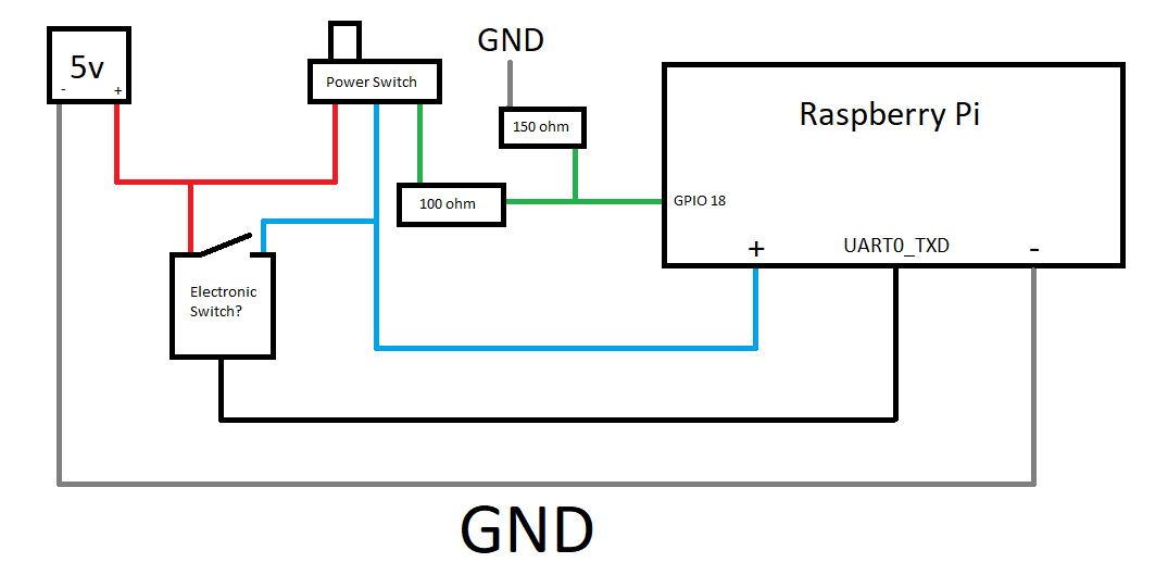
So the red wire is the 5v power line that feeds into the first pin of a basic power switch. The blue wire is the power line connected to the pi in order to power it. So if you turn the power switch to the left, the pi turns on, yay! After the pi turns on, GPIO pin 14 (UART0_TXD) goes high (3.3v) and it won't go low until the pi is in a shutdown state. GPIO pin 14 does this by default, so no extra coding is needed. Pin 14 then feeds into an electrical switch, which will be closed if 3.3v is applied on it's input pin, and open if 0v is applied. That electrical switch then bridges the pin 1 and 2 of the power switch, meaning that if the power switch is flipped off, then power will still be supplied to the pi. Finally, the green wire is connected to pin 3 of the power switch, and is connected to one of the pi's open GPIO pins (pin 18 for example) through a voltage divider. This way, when the power switch is flipped "off" the electrical switch will supply 5v to pin 3 of the power switch, also creating a HIGH value on GPIO 18, informing the pi to initiate a shutdown. Once shutdown, the UART0_TXD pin will stop supplying power to the electrical switch, cutting power to the whole circuit.
This schematic sounds all good, but there is one major problem. I can't find a suitable component to serve as the electrical switch. All that component needs to do, is connect pin 1 and 2 of the power switch, when 3.3v is supplied from GPIO 14.
I've taken a few electrical engineering classes, but I wouldn't call myself proficient at electrical design either. I've currently tried using N-channel MOSFETs and solid state relays to serve as this "electrical switch," but I can't seem to get anything to work. I might just be missing something small, and I might feel stupid later for asking , but do any of you have ANY idea what to use for this switch, and how to wire it up to this schematic? Do you know if this schematic would even work in the first place?
You're input would be greatly appreciated
I've been working on building a simple, yet effective safe shutdown circuit for anyone wanting to not have to worry about corrupting their raspberry pi OS. I've come to a solution of my own but I'm having a dumb electrical problem, so let me walk you through the basic idea, and then I'll get to my issue.
So the red wire is the 5v power line that feeds into the first pin of a basic power switch. The blue wire is the power line connected to the pi in order to power it. So if you turn the power switch to the left, the pi turns on, yay! After the pi turns on, GPIO pin 14 (UART0_TXD) goes high (3.3v) and it won't go low until the pi is in a shutdown state. GPIO pin 14 does this by default, so no extra coding is needed. Pin 14 then feeds into an electrical switch, which will be closed if 3.3v is applied on it's input pin, and open if 0v is applied. That electrical switch then bridges the pin 1 and 2 of the power switch, meaning that if the power switch is flipped off, then power will still be supplied to the pi. Finally, the green wire is connected to pin 3 of the power switch, and is connected to one of the pi's open GPIO pins (pin 18 for example) through a voltage divider. This way, when the power switch is flipped "off" the electrical switch will supply 5v to pin 3 of the power switch, also creating a HIGH value on GPIO 18, informing the pi to initiate a shutdown. Once shutdown, the UART0_TXD pin will stop supplying power to the electrical switch, cutting power to the whole circuit.
This schematic sounds all good, but there is one major problem. I can't find a suitable component to serve as the electrical switch. All that component needs to do, is connect pin 1 and 2 of the power switch, when 3.3v is supplied from GPIO 14.
I've taken a few electrical engineering classes, but I wouldn't call myself proficient at electrical design either. I've currently tried using N-channel MOSFETs and solid state relays to serve as this "electrical switch," but I can't seem to get anything to work. I might just be missing something small, and I might feel stupid later for asking
You're input would be greatly appreciated