White screen when testing BW screen.
White screen when testing BW screen.
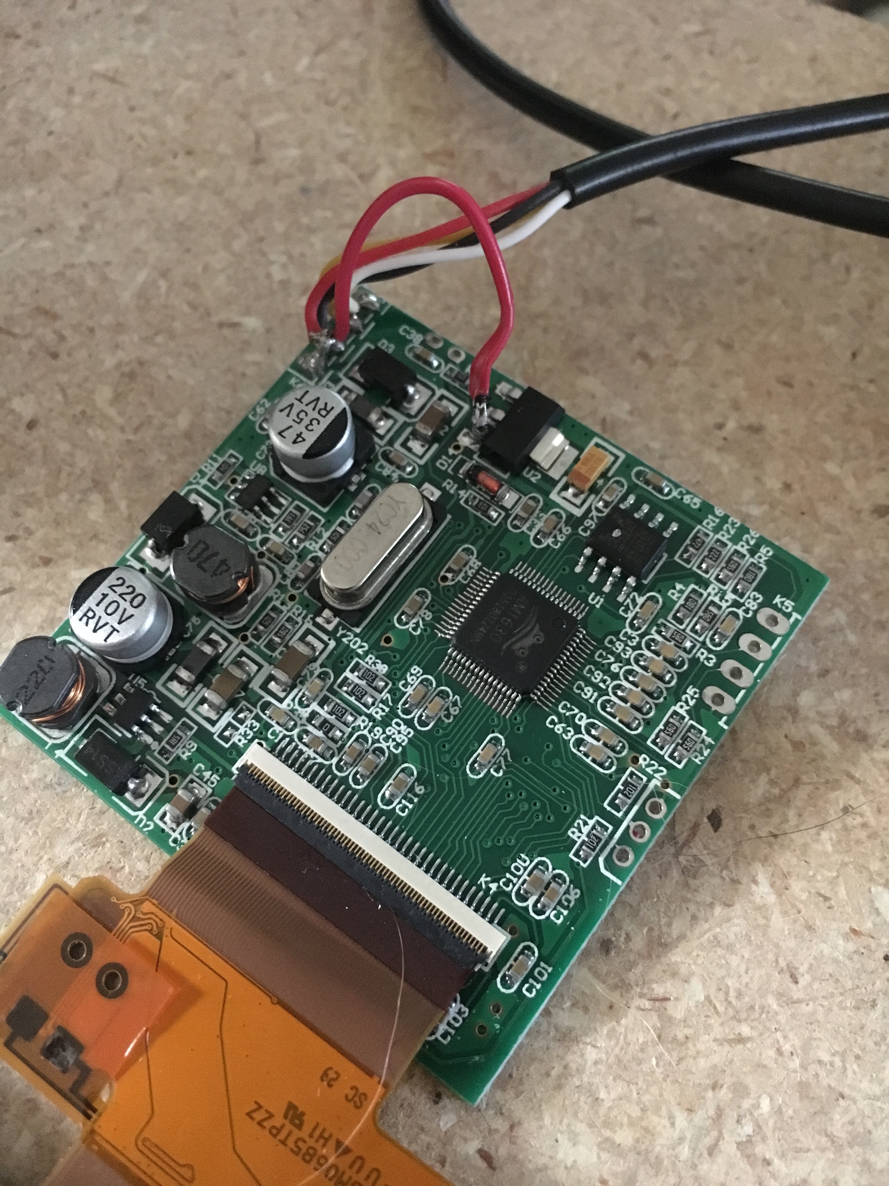
Okay so I've been wracking my brain over this for most of the afternoon, but I can't seem to get the BW backup camera screen to give me a picture. The screen is variant 8 on the wiki and I have tried both 5 volt modifications. Everything is wired up correctly and I can't find any shorts but I still end up with a white screen, I tried formatting my SD card and adding retro pi for pi 1/0 and it still doesn't seem to work, any ideas before I order another screen off amazon to try again?
- Attachments
-
- IMG_1399.JPG (2.64 MiB) Viewed 12366 times
-
- IMG_1398.JPG (2.12 MiB) Viewed 12366 times
-
onesojourner
- Posts: 101
- Joined: Tue Dec 13, 2016 10:23 am
- Has thanked: 21 times
- Been thanked: 12 times
Re: White screen when testing BW screen.
I have had all kinds of problems with these screens. I have gotten 1 of 4 to work and it is constantly blinking and staticey. The one I have gotten to work I did not need the jumper. I just removed the original power and and went straight to the 5 v input. Have you tested your pi with another composite screen?
Re: White screen when testing BW screen.
Straight to 5v as in just plugging it in as is? And no I haven't tested it with a different screen yet, I've been meaning to but work has kept me from having time to work on this project
Re: White screen when testing BW screen.
I'm having the same issue with the same screen. 
I'm using "method 1" as listed on the wiki. Any ideas?
I'm using "method 1" as listed on the wiki. Any ideas?
Re: White screen when testing BW screen.
OP any luck? I am also having this exact same issue with the exact same screen.
-
cobramike
- Posts: 230
- Joined: Sat Oct 29, 2016 12:31 am
- Location: Gelderland, Netherlands
- Has thanked: 55 times
- Been thanked: 60 times
Re: White screen when testing BW screen.
Check if your solder is not touching any other components.
Whooo Stop befor ask in a post. First use the search or the wiki befor you make a topic.. Just saying.........
Re: White screen when testing BW screen.
I checked that pretty carefully and the only questionable spot place where it is really close to other components is on the controller board modification (change over to 5v)
I also tried swapping the Yellow and White connections on the Pi but that didnt work.
HDMI input works well so I dont think it is a RPi issue,
I made sure the ribbon cable was attached correctly too.
I'm just at a loss.
I saw a post that said only one composite connection is necessary on these screens (either white OR yellow). Is it possible that using both is causing some sort of interference?
I cant imagine that being the issue because how would the screen ever function normally if they are both plugged in?
The only thing I have not yet tried is the Second modification method from the Wiki.
http://sudomod.com/wiki/images/a/a5/IMG_0480.JPG
If I'm looking at this picture correctly, it seems like the red 5v wire is soldered to the GROUND connection on the board and then bridged with solder to the 12V input and over to the chip. That seems really weird to me, Why are the ground and power connected in the same port? It just seems counter-intuitive to me.
*EDIT*
I also just found this, would it help?
Setting up the software
First things first: either SSH into your Raspberry Pi, or open up a terminal window.
Start by opening config.txt in your editor of choice. We’ll be using nano:
sudo nano /boot/config.txt
1
sudo nano /boot/config.txt
There are two lines in the file that you need to edit. Firstly, you need to remove the comment ‘#’ from the following line:
#sdtv_mode=2
1
#sdtv_mode=2
So it should now look like this:
sdtv_mode=2
1
sdtv_mode=2
Then we need to add a comment ‘#’ to the following line:
hdmi_force_hotplug=1
1
hdmi_force_hotplug=1
So it should now look like this:
# hdmi_force_hotplug=1
1
# hdmi_force_hotplug=1
That’s it. Remember to save your file – if you used nano, press CTRL+X to exit; then, when asked if you want to save changes, enter Y then press RETURN.
Now you can plug your RCA cable into your TV/monitor, and you should hopefully see the video output.
-
dryja123

- Posts: 1076
- Joined: Tue May 09, 2017 5:34 pm
- Location: Central NJ
- Has thanked: 239 times
- Been thanked: 553 times
Re: White screen when testing BW screen.
I'd be curious to see how he's wired up to the Pi. Also, as cobramike suggested, the soldering looks suspect. Particularly the white composite cable has copper exposed.
Guide for troubleshooting mintyPi power problems: http://www.sudomod.com/forum/viewtopic.php?f=34&t=4115
My mintyPi builds: http://www.sudomod.com/forum/viewtopic.php?f=32&t=3985
My mintyPi builds: http://www.sudomod.com/forum/viewtopic.php?f=32&t=3985
-
cobramike
- Posts: 230
- Joined: Sat Oct 29, 2016 12:31 am
- Location: Gelderland, Netherlands
- Has thanked: 55 times
- Been thanked: 60 times
Re: White screen when testing BW screen.
Ya when i look @ his solder work. Its not nice. Also the pic is not that clear to see. Clean your board up. And please make a new pic of the aria where you solderd. Thanks buddy
Whooo Stop befor ask in a post. First use the search or the wiki befor you make a topic.. Just saying.........
-
the antithesis
- Posts: 22
- Joined: Sat Jun 04, 2016 10:12 am
- Been thanked: 5 times
Re: White screen when testing BW screen.
Possibly. I can't be sure. But these back up camera screen have two channels, or whatever, so they can take in two feeds. Most likely back up camera and DVD player for the kids. So only use one, yellow will do, and then make sure your ground (black) also goes to the Pi. So power (5v), ground, and signal need to all come from the same place. Once hooked up, plug the screen's menu buttons back in and if you still don't get a picture, try switching to AV2 or whatever it is on your screen.
But do show us how it's hooked up to the Pi. We'll need to see the whole circuit to be able to tell what could be wrong.
Who is online
Users browsing this forum: No registered users and 1 guest