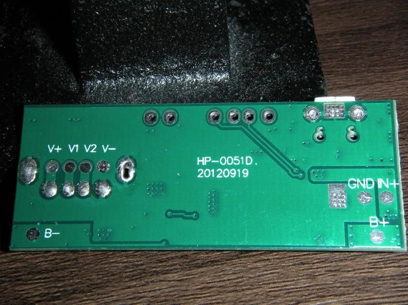
Power boost/charger wiring

Hardware-related questions that don't fit into any of the specialized hardware categories go here.
User avatar
gargoyle67
Posts: 73
Joined: Fri Jun 17, 2016 3:13 pm
Has thanked: 48 times
Been thanked: 16 times

Re: Power boost/charger wiring

Post by gargoyle67 » Thu Jul 14, 2016 1:11 am

Oxodao wrote:180uA is pretty insane IMO so the best bet would be to cut the trace linking to the step up converter and replacing it by a switch... Easier said than done I know
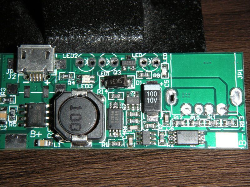
Here are some close up pics of the board, please note I've removed the usb 5v out plug with my trusty heat station :) I didn't think it had traces on the top of the board untill I looked at the below pics (there that tiny !)


ImageImage

User avatar
BadBert
Posts: 377
Joined: Wed Jun 29, 2016 4:14 am
Location: Hoogerheide, Netherlands
Has thanked: 100 times
Been thanked: 61 times
Contact:

Re: Power boost/charger wiring

Post by BadBert » Thu Jul 14, 2016 5:10 am

If someone finds out what traces to cut and place the switch.... please let us know!
My first GBZ build -=HERE=- -> Became a gift to my little brother!
My 2nd GBZ build -=WIP HERE=- -> going with HDMI!

User avatar
Oxodao
Posts: 131
Joined: Wed Jun 01, 2016 11:35 am
Location: 127.0.0.1
Has thanked: 4 times
Been thanked: 30 times
Contact:

Re: Power boost/charger wiring

Post by Oxodao » Thu Jul 14, 2016 5:17 am

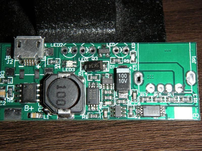
Without the board in the hands it's pretty difficult to test continuity, anyway the chip on the far left is the charger. The one in the middle and one on the right are battery protection. Could you give me what's written on the small in the middle please?

Mine is on her way so... I just need to wait...
Though according to the pcb's density it could be pretty hard to cut

I dont know much about electronic so I might take few moments to RE it :/
Arduino sketch for the gamepad (Teensy replacement): http://github.com/oxodao/GBZGamepad

User avatar
BadBert
Posts: 377
Joined: Wed Jun 29, 2016 4:14 am
Location: Hoogerheide, Netherlands
Has thanked: 100 times
Been thanked: 61 times
Contact:

Re: Power boost/charger wiring

Post by BadBert » Thu Jul 14, 2016 5:40 am

mine is also on its way, so i cant check what is printed on the chips :(
My first GBZ build -=HERE=- -> Became a gift to my little brother!
My 2nd GBZ build -=WIP HERE=- -> going with HDMI!

User avatar
gargoyle67
Posts: 73
Joined: Fri Jun 17, 2016 3:13 pm
Has thanked: 48 times
Been thanked: 16 times

Re: Power boost/charger wiring

Post by gargoyle67 » Thu Jul 14, 2016 6:14 am

Oxodao wrote: Mine is on her way so... I just need to wait...
Though according to the pcb's density it could be pretty hard to cut
I dont know much about electronic so I might take few moments to RE it :/
It would be impossible I'm guessing to cut and solder to a trace that small, I'm guessing the switch/mod will have to be on one of the chips legs....
The chip numbers from left to right of the big round 100 coil ?
4056ES/6154SD
8205A/SI545

Here is the hires version ;) (Save it and zoom in rotate)
Image

User avatar
Oxodao
Posts: 131
Joined: Wed Jun 01, 2016 11:35 am
Location: 127.0.0.1
Has thanked: 4 times
Been thanked: 30 times
Contact:

Re: Power boost/charger wiring

Post by Oxodao » Thu Jul 14, 2016 7:14 am

Image
Arduino sketch for the gamepad (Teensy replacement): http://github.com/oxodao/GBZGamepad

User avatar
gargoyle67
Posts: 73
Joined: Fri Jun 17, 2016 3:13 pm
Has thanked: 48 times
Been thanked: 16 times

Re: Power boost/charger wiring

Post by gargoyle67 » Thu Jul 14, 2016 8:30 am

The ? chip is>
DW02/7777Z
I think as I had to use 2 magnifying glasses to read it !

mwass
Posts: 14
Joined: Mon Jul 18, 2016 7:49 pm
Has thanked: 10 times
Been thanked: 1 time

Re: Power boost/charger wiring

Post by mwass » Tue Jul 19, 2016 4:48 pm

the adafruit powerboost is available absolutely nowhere and adafruit doesnt seem to be restocking it anytime soon so I bought the alternate one but since this is my first build and I have absolutely no idea what im doing. What is a good way to hook up the battery to it because it doesnt seem like there is a port to hook up the lithium ion battery to. Also how do you wire up the powerswitch so it charges while its off.

User avatar
Oxodao
Posts: 131
Joined: Wed Jun 01, 2016 11:35 am
Location: 127.0.0.1
Has thanked: 4 times
Been thanked: 30 times
Contact:

Re: Power boost/charger wiring

Post by Oxodao » Tue Jul 19, 2016 6:37 pm

mwass wrote:the adafruit powerboost is available absolutely nowhere and adafruit doesnt seem to be restocking it anytime soon so I bought the alternate one but since this is my first build and I have absolutely no idea what im doing. What is a good way to hook up the battery to it because it doesnt seem like there is a port to hook up the lithium ion battery to. Also how do you wire up the powerswitch so it charges while its off.
If you have no idea of what you are doing, you'd better do nothing. Take your time and read the internet, batteries can be pretty dangerous.

You have to cut the JST connector from the battery, then solder the positive side of the battery on "B+" and negative on "B-". You will have a sort of power bank working. Then you just remove the USB socket (The biggest) and solder your + and - wire on the board, that will be your power output. Be really careful to not short anything out
Arduino sketch for the gamepad (Teensy replacement): http://github.com/oxodao/GBZGamepad

User avatar
BadBert
Posts: 377
Joined: Wed Jun 29, 2016 4:14 am
Location: Hoogerheide, Netherlands
Has thanked: 100 times
Been thanked: 61 times
Contact:

Re: Power boost/charger wiring

Post by BadBert » Wed Jul 20, 2016 12:23 am

You can also solder a couple of leads to the board, with the connector on it, on wich you can plug in your battery.
If you make the leads long enough, you can keep the battery easily removable! (that's what i'm planning to do)
My first GBZ build -=HERE=- -> Became a gift to my little brother!
My 2nd GBZ build -=WIP HERE=- -> going with HDMI!

Post Reply

Who is online

Users browsing this forum: No registered users and 1 guest