@Camble How does that pin (I think it's 22 from reading your posts) act during a reboot? Using the TXD pin, if I restart the Pi, the pin goes low and kills power to everything. I then have to power it back on. I was going to remedy this by adding a capacitor to the gate to keep the mosfet enabled for an extra second or two, but if your pin stays high then it would be a better solution.Camble wrote:@othermod I originally borrowed the UART pin idea from @Popcorn but we decided using a BCM pin was stable in half the time during boot up.
The schematic I've designed to go with the banggood supply is essentially the same as your dual MOSFET setup.
Pi in a PSP
-
othermod

- Posts: 43
- Joined: Wed Aug 03, 2016 7:03 pm
- Location: https://t.me/pump_upp
- Has thanked: 6 times
- Been thanked: 21 times
- Contact:
Re: Pi in a PSP
-
Camble

- Posts: 885
- Joined: Thu May 05, 2016 2:31 am
- Location: Scotland
- Has thanked: 269 times
- Been thanked: 488 times
Re: Pi in a PSP
@othermod Good question. I'll have to check.
Also, you need to add the following line into /boot/config.txt
Also, you need to add the following line into /boot/config.txt
Code: Select all
dtoverlay=gpio-poweroff,gpiopin=22,active_low="y"-
othermod
- Posts: 43
- Joined: Wed Aug 03, 2016 7:03 pm
- Location: https://t.me/pump_upp
- Has thanked: 6 times
- Been thanked: 21 times
- Contact:
Re: Pi in a PSP
@Camble Okay I've been reading through the posts, trying to wrap my head around everything. Does the config code only make the GPIO pin go low after shutdown? Also, as I understood it, the GPIO is in an unstable floating state during bootup, and that's why I used the TX (and because it saved a GPIO pin for something else). Am I wrong about that?Camble wrote:@othermod Good question. I'll have to check.
Also, you need to add the following line into /boot/config.txt
Code: Select all
dtoverlay=gpio-poweroff,gpiopin=22,active_low="y"
Also, I'm looking at the gbz_power_monitor.py file that @popcorn posted and it appears that he solved another problem I had. I've made a very simple low-battery warning circuit using an LM393 dual comparator. What is does is compare a reference voltage (like the 3.3v from the Pi) to the battery voltage. If the battery voltage drops below the reference voltage, it switches an output high or low depending on your preference. Right now this output supplies the GND to a low-battery LED. I intended for the other output from the LM393 to connect to the same pin that detects a falling edge and issue a shutdown, but I know that if the battery is low when the OS is booted then the GPIO pin will stay low and there will be no falling edge to detect. I assume he resolved this with this code:
Code: Select all
81 def main():
82   #if the Low Battery LED is active when the program launches, handle it
83   if GPIO.input(batteryGPIO) is 0:
84     lowBattery(batteryGPIO)
85

86   #if the Power Switch is active when the program launches, handle it
87   if GPIO.input(powerGPIO) is 0:
88     powerSwitch(powerGPIO)
Everything I'm designing is based around using the banggood power supply, since the powerboost isn't cheap. That's why I made the LM393 circuit.
I'm very excited by what I'm seeing on this site. You guys have solved many of the problems I've been working on. I hope to be able to return the favor.
-
Camble
- Posts: 885
- Joined: Thu May 05, 2016 2:31 am
- Location: Scotland
- Has thanked: 269 times
- Been thanked: 488 times
-
Camble
- Posts: 885
- Joined: Thu May 05, 2016 2:31 am
- Location: Scotland
- Has thanked: 269 times
- Been thanked: 488 times
Re: Pi in a PSP
I think you're correct, but the UART TX pin seemed to stabilize at 3.3v after 8-10 seconds, whereas a BCM pin with the gpio-poweroff flag set will stabilize after 5 seconds. Again, I'm not sure about reboots.othermod wrote: @Camble Okay I've been reading through the posts, trying to wrap my head around everything. Does the config code only make the GPIO pin go low after shutdown? Also, as I understood it, the GPIO is in an unstable floating state during bootup, and that's why I used the TX (and because it saved a GPIO pin for something else). Am I wrong about that?
This may be helpful
http://sudomod.com/forum/viewtopic.php? ... 330#p10970
-
othermod
- Posts: 43
- Joined: Wed Aug 03, 2016 7:03 pm
- Location: https://t.me/pump_upp
- Has thanked: 6 times
- Been thanked: 21 times
- Contact:
Re: Pi in a PSP
That's strange. I get a stable power-on in under 2 seconds with the TX pin. The small delay is a great feature in my project because it prevents an accidental power-on. Also, if an SD card is not installed, the TX will not pull high and the system will not stay on (another thing I consider a feature). I will have to test to see whether a GPIO pin has the same function. I'm doing more reading about the pins you guys are using. At a minimum, it would be nice to use one pin for both portions of this. Right now I use the TX for pulling the P-mofset up and a regular GPIO pin to detect the power button being pressed and issue a shutdown. Using your method I can possibly avoid using the TX and leave it open for other things.Camble wrote: I think you're correct, but the UART TX pin seemed to stabilize at 3.3v after 8-10 seconds, whereas a BCM pin with the gpio-poweroff flag set will stabilize after 5 seconds. Again, I'm not sure about reboots.
This may be helpful
http://sudomod.com/forum/viewtopic.php? ... 330#p10970
Here is what I'm thinking:
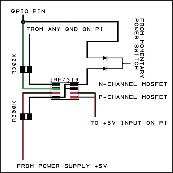
The GPIO pin will be pulled high at bootup and keep the N-mosfet enabled. When the OS is running and the power button is pressed, the GPIO will be pulled down and the shutdown will begin. At this moment, the GPIO will be low and the P-mosfet will be disabled, but the power button should keep the P-mosfet enabled and keep the system powered on. My only question is what will happen when the power button is released. When the button is released, there will no longer be a ground connection keeping the P-mosfet enabled, and I am unsure whether the N-mosfet will come back up quickly enough to supply the GND for the P-mosfet gate. A small capacitor on the P-mosfet gate would probably remedy any issues.
-
Camble
- Posts: 885
- Joined: Thu May 05, 2016 2:31 am
- Location: Scotland
- Has thanked: 269 times
- Been thanked: 488 times
Re: Pi in a PSP
I'm sure TX will do the trick for dual MOSFET, but a fluctuating gate voltage wasn't enough to keep the the JFET off in my safe shutdown circuit.
-
othermod
- Posts: 43
- Joined: Wed Aug 03, 2016 7:03 pm
- Location: https://t.me/pump_upp
- Has thanked: 6 times
- Been thanked: 21 times
- Contact:
Re: Pi in a PSP
Okay so I built the circuit in EveryCircuit. Instead of the TX pin and a GPIO pin, one GPIO pin is used both for pulling the n MOSFET high and for issuing the shutdown command. The only thing it's missing is an emergency shutdown after a long button press.
http://everycircuit.com/circuit/4575239031226368
http://everycircuit.com/circuit/4575239031226368
-
johnweland

- Posts: 26
- Joined: Tue May 10, 2016 12:11 pm
- Has thanked: 3 times
- Been thanked: 8 times
- Contact:
Re: Pi in a PSP
ugh, I'm stoked to see this. especially after watching wermy do his new video building a gbzero with all customer parts no GB actually being used. I've got a psp shell in my amazon cart ready to buy when we have boards ready to go! 
-
othermod
- Posts: 43
- Joined: Wed Aug 03, 2016 7:03 pm
- Location: https://t.me/pump_upp
- Has thanked: 6 times
- Been thanked: 21 times
- Contact:
Re: Pi in a PSP
I'm continuing to work on it, getting closer every day. I got a little distracted because a magazine in the UK is doing a page on the PSPi projectjohnweland wrote:ugh, I'm stoked to see this. especially after watching wermy do his new video building a gbzero with all customer parts no GB actually being used. I've got a psp shell in my amazon cart ready to buy when we have boards ready to go!
Who is online
Users browsing this forum: No registered users and 1 guest