Page 1 of 1
Help with Adafruit 2.8" screen
Posted: Wed Aug 23, 2017 1:53 am
by yungfalafel
Hi everyone! I am trying to use this screen (
https://www.adafruit.com/product/2298) for a Pi Zero "gameboy advance" build but I can't figure out which part I'm supposed to wire the Pi to, and also the gamepad. I am trying to model my project after the Pi Grrl Zero but the screen used looks pretty different (
https://www.adafruit.com/product/2315 ). Do I have to desolder the attached GPIO "stacker"? and even so, what do I do with the GPIO header on the back? Would be great if anyone has any experience with this screen.
Re: Help with Adafruit 2.8" screen
Posted: Wed Aug 23, 2017 2:42 am
by Eccho
Hi,
Welcome to this awesome community.
I have no prior experience with the screen you mention, but if you type PiTFT in the search engine you will see A LOT of topics about people integrating this screen in various builds. I have seen MANY discussions about it in the past. You are more than welcome to react and ask some specific questions to the threads that match your project (I saw already a GB pocket one for example, it might help). If you are lucky you'll find a diagram on how to wire the screen and gamepad (for the latter, look for GBA-related topics and in the show-off corner where some users already made these type of builds).
Best of luck to you!
Re: Help with Adafruit 2.8" screen
Posted: Wed Aug 23, 2017 8:26 am
by abrugsch
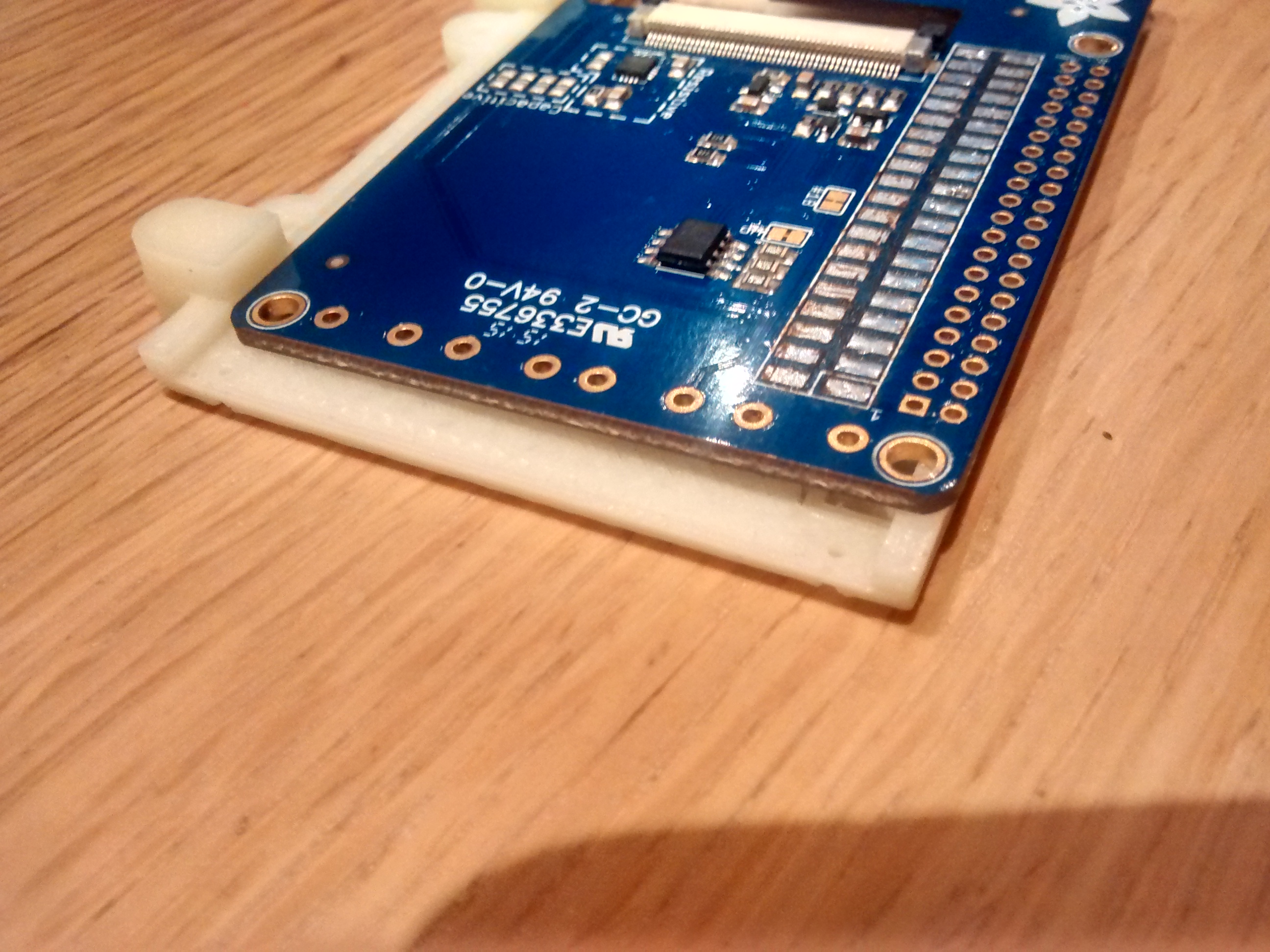
Hi I've got this exact screen and intend to do exactly what you've talked about. I already desoldered the extra connector (which is a passthrough of the main header, so not necessary, just maintains compatability with other GPIO devices)

and you only need to connect the SPI connectors, and a couple of extra GIPO pins for backlight control
The display and touchscreen uses the hardware SPI pins (SCK, MOSI, MISO, CE0, CE1) as well as GPIO #25 and #24.
so you only have to wire up those pins from the Pi GPIO header to the display if you don't want to solder on the header socket.
if you want a better tutorial from adafruit that DOES use that exact display, try this one:
https://learn.adafruit.com/pigrrl-2
Re: Help with Adafruit 2.8" screen
Posted: Wed Aug 23, 2017 11:48 am
by yungfalafel
abrugsch wrote: ↑Wed Aug 23, 2017 8:26 am
Hi I've got this exact screen and intend to do exactly what you've talked about. I already desoldered the extra connector (which is a passthrough of the main header, so not necessary, just maintains compatability with other GPIO devices)

and you only need to connect the SPI connectors, and a couple of extra GIPO pins for backlight control
The display and touchscreen uses the hardware SPI pins (SCK, MOSI, MISO, CE0, CE1) as well as GPIO #25 and #24.
so you only have to wire up those pins from the Pi GPIO header to the display if you don't want to solder on the header socket.
if you want a better tutorial from adafruit that DOES use that exact display, try this one:
https://learn.adafruit.com/pigrrl-2
How did you manage to desolder the pins?
Re: Help with Adafruit 2.8" screen
Posted: Wed Aug 23, 2017 4:00 pm
by abrugsch
Usual desoldering method... Solder sucker, desoldering braid... Lift off the black plastic spacer and it becomes quite easy. You don't need to remove it though...
