Power boost/charger wiring
-
gargoyle67

- Posts: 73
- Joined: Fri Jun 17, 2016 3:13 pm
- Has thanked: 48 times
- Been thanked: 16 times
Re: Power boost/charger wiring
I only paid £2.19 each for my boards so I'm not really worried if I have to buy the Adafruit one  I just wish someone would do a detailed wiring of this alternative board.....
-
Fleder

- Posts: 849
- Joined: Thu May 05, 2016 9:04 am
- Location: Germany
- Has thanked: 183 times
- Been thanked: 258 times
Re: Power boost/charger wiring
I am not a 100% sure, as i am not that far because of lack of time, but i think you can just wire an appropriate switch between the V+ of the Battery and the Power Supply and then mount it where the original one was.


-
gargoyle67
- Posts: 73
- Joined: Fri Jun 17, 2016 3:13 pm
- Has thanked: 48 times
- Been thanked: 16 times
Re: Power boost/charger wiring
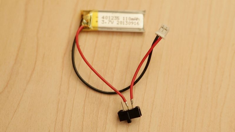
So the wiring of switch battery would be something like this below, But instead of the 2 pin connector in the pic it would connect to the booster board's battery + and - , Then you would connect ground and positive from the 5v output from the power booster to the project board and power what you need.

-
Oxodao

- Posts: 131
- Joined: Wed Jun 01, 2016 11:35 am
- Location: 127.0.0.1
- Has thanked: 4 times
- Been thanked: 30 times
- Contact:
Re: Power boost/charger wiring
Nope that's not a good idea, you will be able to charge the battery ONLY when the gameboy is on... Though you won't since the chip on it is not meant to do that...
Arduino sketch for the gamepad (Teensy replacement): http://github.com/oxodao/GBZGamepad
-
BadBert

- Posts: 377
- Joined: Wed Jun 29, 2016 4:14 am
- Location: Hoogerheide, Netherlands
- Has thanked: 100 times
- Been thanked: 61 times
- Contact:
Re: Power boost/charger wiring
According to the specs.... It ISOxodao wrote:Nope that's not a good idea, you will be able to charge the battery ONLY when the gameboy is on... Though you won't since the chip on it is not meant to do that...
as to be found here:This PCB also support charging the battery, simply supply a 5V micro USB source to the charging input and it will charge the connected battery to 4.2V.
http://m.banggood.com/37V-Liion-Battery ... 37201311DI
My first GBZ build -=HERE=- -> Became a gift to my little brother!
My 2nd GBZ build -=WIP HERE=- -> going with HDMI!
My 2nd GBZ build -=WIP HERE=- -> going with HDMI!
-
Oxodao
- Posts: 131
- Joined: Wed Jun 01, 2016 11:35 am
- Location: 127.0.0.1
- Has thanked: 4 times
- Been thanked: 30 times
- Contact:
Re: Power boost/charger wiring
In this case, my bad. The best way to do that is to find out which part is the 5v booster and which one is the charger. Cut the trace between the battery and the boost and add a switch or any other way to handle the on/off and you're good to go
Arduino sketch for the gamepad (Teensy replacement): http://github.com/oxodao/GBZGamepad
-
gargoyle67
- Posts: 73
- Joined: Fri Jun 17, 2016 3:13 pm
- Has thanked: 48 times
- Been thanked: 16 times
Re: Power boost/charger wiring
mmm I'll prob see if someone else does the cut trace/switch thing as I wouldn't have a clue where the 5v to charger trace is and I wouldn't want to screw it upOxodao wrote:In this case, my bad. The best way to do that is to find out which part is the 5v booster and which one is the charger. Cut the trace between the battery and the boost and add a switch or any other way to handle the on/off and you're good to go
http://www.sudomod.com/forum/viewtopic.php?f=8&t=651
-
Oxodao
- Posts: 131
- Joined: Wed Jun 01, 2016 11:35 am
- Location: 127.0.0.1
- Has thanked: 4 times
- Been thanked: 30 times
- Contact:
Re: Power boost/charger wiring
Yeah I know, I will order one when I can though this will be long so meanwhile I suggest you take a look at it
Arduino sketch for the gamepad (Teensy replacement): http://github.com/oxodao/GBZGamepad
Re: Power boost/charger wiring
Put a switch between battery+ and power board doesn't worked.
There is a 180uA current when nothing is using 5v output.
So each time you shut down then turn up the battery, you need to have the power board on charge.During first use first connect input (mini USB) to a 5V source prior to connecting any battery. .
There is a 180uA current when nothing is using 5v output.
-
Oxodao
- Posts: 131
- Joined: Wed Jun 01, 2016 11:35 am
- Location: 127.0.0.1
- Has thanked: 4 times
- Been thanked: 30 times
- Contact:
Re: Power boost/charger wiring
Inb4Nosfay wrote:Put a switch between battery+ and power board doesn't worked.
So each time you shut down then turn up the battery, you need to have the power board on charge.During first use first connect input (mini USB) to a 5V source prior to connecting any battery. .
There is a 180uA current when nothing is using 5v output.
180uA is pretty insane IMO so the best bet would be to cut the trace linking to the step up converter and replacing it by a switch... Easier said than done I knowOxodao wrote:Nope that's not a good idea, you will be able to charge the battery ONLY when the gameboy is on...
EDIT: Ooops I thought it was mA haha so no that is correct you can let is as is I think
Arduino sketch for the gamepad (Teensy replacement): http://github.com/oxodao/GBZGamepad
Who is online
Users browsing this forum: No registered users and 1 guest