Page 1 of 4
Power boost/charger wiring
Posted: Tue Jul 12, 2016 11:40 am
by gargoyle67
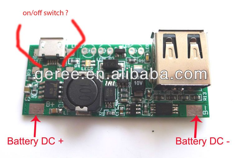
I have the pictured power booster instead of the Adafruit 1000c one, Has anyone got a wiring diagram of how they wired it at all ?
Some of the questions I have are> do I wire the on/off switch to the +/- behind the micro usb charge in port as I've highlighted in the picture ?
As this board doesn't have the enable pin as on the Adafruit board.
The battery connects to the DC+/DC- , Should I connect a the battery instead to a prototyping board instead and then loop wires back from that board to the DC+/DC- so I can also use the prototyping board to power my pi board ?
Noob questions I know but hay I'm fairly noobish

Re: Power boost/charger wiring
Posted: Tue Jul 12, 2016 1:08 pm
by BadBert
Interested in this too

Re: Power boost/charger wiring
Posted: Tue Jul 12, 2016 7:48 pm
by Nosfay
Hi,
do I wire the on/off switch to the +/- behind the micro usb charge in port as I've highlighted in the picture ?
No, your on/off switch will be at the board output (+5v).
The battery connects to the DC+/DC- , Should I connect a the battery instead to a prototyping board instead and then loop wires back from that board to the DC+/DC- so I can also use the prototyping board to power my pi board ?
Connect your battery directly to DC+/DC-, because lithium battery have 3.7v current and raspberry need 5v.
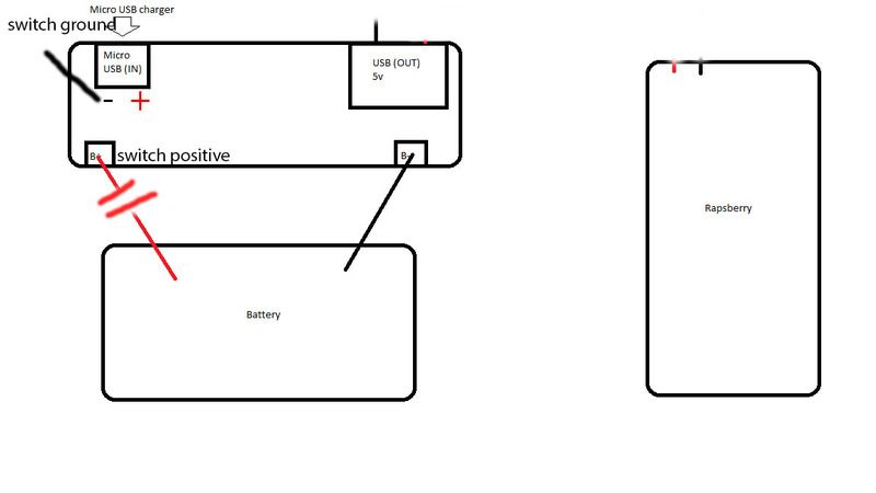
Here is a little diagram I did for you

You can use a prototyping board after the on/off switch to split your 5v current to supply your rapsberry, screen and sound amp.
To wire +5v output, you can desolder USB port and use it pin, or just solder on pin with v+ v- or something like that on the other board side.
Re: Power boost/charger wiring
Posted: Wed Jul 13, 2016 12:32 am
by gargoyle67
Nice thank you for taking the time.
Re: Power boost/charger wiring
Posted: Wed Jul 13, 2016 1:52 am
by Fleder
If you plan on using the graceful shutdown method, okay.
But if you do not, you should wire the on/off switch (if you want to cut off the battery to stop it from being drained)
between the battery and the Power Supply, not at the output.
Sure, it is not much, but the Power Supply will still be powered the other way and drains a tiny amount of power.
Make sure your on/off switch can cope with the mAh.
Re: Power boost/charger wiring
Posted: Wed Jul 13, 2016 6:51 am
by gargoyle67
Fleder wrote:If you plan on using the graceful shutdown method, okay.
But if you do not, you should wire the on/off switch (if you want to cut off the battery to stop it from being drained)
between the battery and the Power Supply, not at the output.
Sure, it is not much, but the Power Supply will still be powered the other way and drains a tiny amount of power.
Make sure your on/off switch can cope with the mAh.
Thanks Fleder, I did wonder about the battery drain, The booster isn't Adafruit so I don't think I can use the graceful shut down.
I'll be using a 3000mah and the original GB on/off switch not sure what mah load it can take ?
So for the switch I should attach ground to my micro ac in - as in my original post above and the positive switch red wire between the battery's + cable and the boosters + solder point ?
like this> ?
Re: Power boost/charger wiring
Posted: Wed Jul 13, 2016 7:29 am
by Fleder
gargoyle67 wrote:Thanks Fleder, I did wonder about the battery drain, The booster isn't Adafruit so I don't think I can use the graceful shut down.
I'll be using a 3000mah and the original GB on/off switch not sure what mah load it can take ?
So for the switch I should attach ground to my micro ac in - as in my original post above and the positive switch red wire between the battery's + cable and the boosters + solder point ?
like this> ?
I am not sure about the original one, but the alternatives are usually around 500mAh,
so they might not be suited to sustain 1/2A while charging.
They might work, but could get hot, that depends on the thickness of the material that is used for the contact pads.
Keep in mind that you have to shutdown the Pi manually with the EmulationStation or via terminal command,
do not just toggle the switch to cut the power. Shut it down, then toggle the switch.
If you want the switch to just cut the power completely, wire it between the V+ of the battery and the Power Supply Module.
I am not talking about the original Power Switch, i am talking about another one that cuts the power from the battery to the power supply.
If you want to know how to wire the original on/off switch, just watch wermys youtube videos.
Re: Power boost/charger wiring
Posted: Wed Jul 13, 2016 7:49 am
by BadBert
If you put the switch inbetween the battery + and + on the board, you have to remember to keep it switched on while charging...
I thought the alternativewould also have an pin tondisable/enable.... Because bow, i dont know if my switch can cope with the power that iis draw.
Is it best to put it in the battery power line? Or the 5v out from usb?
Re: Power boost/charger wiring
Posted: Wed Jul 13, 2016 7:51 am
by gargoyle67
Thanks, Yes I realize about shutting down emustation first as to not cause corruption on the SD card
The trouble with following wermys video guide is my boost board isn't a Adafruit one so I haven't got an (EN) pin on it

Re: Power boost/charger wiring
Posted: Wed Jul 13, 2016 8:03 am
by BadBert
I bought the same board as it was stated as alternative on the wiki.....
Now i am thinking i should have bought the adafruit one!

