All in One PCB Support Thread
Re: All in One PCB Support Thread
I too ordered 75Ω 0806 in the hope to boost audio a bit louder. I'll keep you informed of the results (but as it's coming from overseas, it may take some time). I however notice some high pitched noise since the mod, but it's really faint, so I don't mind.
-
Mischief

- Posts: 225
- Joined: Sat May 21, 2016 7:50 am
- Location: Wolverhampton, UK
- Has thanked: 29 times
- Been thanked: 69 times
Re: All in One PCB Support Thread
I haven't noticed any high pitch noise but I have used shielded wire and grounded it either end for the PWM wires, only thing that happens is every so often there is a very low pop sound but it's not constant so can live with that. PWM audio is never going to be perfect all I am after is an increase in volume without audio cutting out on some of the games I play.Boubobo wrote:I too ordered 75Ω 0806 in the hope to boost audio a bit louder. I'll keep you informed of the results (but as it's coming from overseas, it may take some time). I however notice some high pitched noise since the mod, but it's really faint, so I don't mind.
-
mariovisic
- Posts: 15
- Joined: Fri Jan 13, 2017 10:30 pm
- Been thanked: 15 times
Re: All in One PCB Support Thread
Edit:
Threw a pair of 5 ohm resistors through to the speaker. Volume is great on the speaker now. The volume is very high on the headphone jack but it's much easier to adjust the volume slider just right. There is a lot of noise on the headphone jack, will change the PWM to shielded cables if it starts to annoy me.
Thanks for everyone's help. Here is what my bodge job looks like. Will need to move the resistors off the board a little as they're pretty close to the speaker positive (+) pad.
Ignore the little looped yellow cable, I took off a pad while trying to change out to another headphone jack.
- Attachments
-
- bodge.jpg (2.51 MiB) Viewed 9921 times

Re: All in One PCB Support Thread
sigh ... doesn't work with 75Ω ... sound ist still shitty. I'm giving up and will order two USB soundcards ...
@Helder: is there any way to get two correct 5-pin headphone jacks? Doesn't work for me with briding the 6th pin
@Helder: is there any way to get two correct 5-pin headphone jacks? Doesn't work for me with briding the 6th pin
-
Helder

- Trailblazer

- Posts: 2985
- Joined: Thu May 05, 2016 8:33 am
- Location: Rogers, AR
- Has thanked: 1459 times
- Been thanked: 3114 times
Re: All in One PCB Support Thread
PM me your shipping info and I'll sen them out.Paddy wrote:sigh ... doesn't work with 75Ω ... sound ist still shitty. I'm giving up and will order two USB soundcards ...
@Helder: is there any way to get two correct 5-pin headphone jacks? Doesn't work for me with briding the 6th pin
Chat with me and other members On Discord
Don't contact me about obtaining my board files (as you will not get them). If my Boards or PCB Kits are sold out, they will be restocked as soon as I can get them and there is demand for them. You can join the mailing list on my Website to be notified when they are available.
Helder's Game Tech Website
We will not support any cloned work so don't come to us with technical issues to resolve, go talk to the cloner for help.
Re: All in One PCB Support Thread
Hi guys, having some issues too with this speaker... So headphone jack is all working well (only a little bit of noise), however the speaker is really quiet and I believe some of you have had the same issue.
Problem is I'm a massive noob when it comes to electronics, so wondering if people can give me some helps in regard to this issue. Been looking through this post but can't seem to find a straight forward solution. So below if a photo of @Helder board, and I've seen people mentioning changing resistors and attaching wires etc. but really unsure what I should do :/
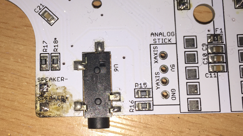
p.s. I apologise for my awful soldering... I ended up marking the board as you can see...
THANK YOU!!!!
Problem is I'm a massive noob when it comes to electronics, so wondering if people can give me some helps in regard to this issue. Been looking through this post but can't seem to find a straight forward solution. So below if a photo of @Helder board, and I've seen people mentioning changing resistors and attaching wires etc. but really unsure what I should do :/
p.s. I apologise for my awful soldering... I ended up marking the board as you can see...
THANK YOU!!!!
Re: All in One PCB Support Thread
To try the fix explained in previous posts, you should be confident enough to solder on the side of those 0805 resistors. If not, is there anybody that could do it for you ? (I don't know where you live, but maybe somebody here could help).dcex1 wrote:Hi guys, having some issues too with this speaker... So headphone jack is all working well (only a little bit of noise), however the speaker is really quiet and I believe some of you have had the same issue.
The idea, is, in addition of the required wiring explained in the original assembly post, you have to Solder something like

(With two 50Ohm resistors)
-
Helder
- Trailblazer
- Posts: 2985
- Joined: Thu May 05, 2016 8:33 am
- Location: Rogers, AR
- Has thanked: 1459 times
- Been thanked: 3114 times
Re: All in One PCB Support Thread
That's an older version of the board because I used 200 ohm resistors on that version, best thing to do is use lower value resistors in place of those on there right now so you might have to remove them completely. Some might wonder why the value is high on this board version and that was to find a middle ground for the headphone output and speaker level but not everyone uses the same speaker so volumes usually will vary.dcex1 wrote:Hi guys, having some issues too with this speaker... So headphone jack is all working well (only a little bit of noise), however the speaker is really quiet and I believe some of you have had the same issue.
Problem is I'm a massive noob when it comes to electronics, so wondering if people can give me some helps in regard to this issue. Been looking through this post but can't seem to find a straight forward solution. So below if a photo of @Helder board, and I've seen people mentioning changing resistors and attaching wires etc. but really unsure what I should do :/
p.s. I apologise for my awful soldering... I ended up marking the board as you can see...
THANK YOU!!!!
You can remove those resistors easily by holding a soldering iron on the left side of the resistor's pad and hold it against the resistor till the solder on both sides softens up and it will slide right off.
Then you can use a regular resistor of a value of around 75ohms and solder each leg to one of the pads ( a few pages back had an image of someone doing this) and the volume should go up on the speaker side.
Chat with me and other members On Discord
Don't contact me about obtaining my board files (as you will not get them). If my Boards or PCB Kits are sold out, they will be restocked as soon as I can get them and there is demand for them. You can join the mailing list on my Website to be notified when they are available.
Helder's Game Tech Website
We will not support any cloned work so don't come to us with technical issues to resolve, go talk to the cloner for help.
Don't contact me about obtaining my board files (as you will not get them). If my Boards or PCB Kits are sold out, they will be restocked as soon as I can get them and there is demand for them. You can join the mailing list on my Website to be notified when they are available.
Helder's Game Tech Website
We will not support any cloned work so don't come to us with technical issues to resolve, go talk to the cloner for help.
-
Lphillimore

- Posts: 993
- Joined: Sat Jan 07, 2017 7:03 pm
- Location: Perth, WA
- Has thanked: 796 times
- Been thanked: 527 times
Re: All in One PCB Support Thread
Help needed guys!
So here's the thing.... Finished my build a couple of months ago (see signature) and everything working fine.
Only issue I had was Audio with the AIO board. This was fixed as per @tomatoflames fix adding 75ohm resistors to R15 and R16 then bridging and attaching to speaker as per:
This worked perfectly and I've had no issues to date.
Recently decided to re expose the mini HDMI port that i previously covered up. Opened the case, re aligned the Pi, fixed it down and closed the case.
Oddly I noticed audio dropouts when i increased volume after this. Not terrible but annoying and noticeable. Thought i must have knocked a resistor perhaps, solder joint etc. Opened up, couldn't see anything. Ended up re making the bridged 75ohm resistors on perf board and rewiring. Still no joy.
Decided while I was in there id swap my pi for a new pi zero W and in the process re-wired everything including PWM wires and a new voulme pot.
All working but again...drop outs on sound when loud / normal volume.
Sometimes its not too bad at all. Went to bed last night thinking it was all ok. This morning it's worse than ever.
What have i overlooked?!
UPDATE:
Further scouring of these forums and I found this post by @enemone:
'ANYONE HAVING CHOPPY SOUND!
I fixed that issue by de-soldering my connection to the left or right channel it will make your speaker a true mono and will avoid both inputs trying to play at once through the same speaker which causes the choppy audio through the speaker.'
From memory I noted my Left Channel Out wire was disconnected from my volume pot when I opened up the case to fix the HDMI but I assumed I did this opening it.....perhaps it was already disconnected and by re-connecting it I inadvertently caused this issue. Will de-solder it tonight and test. I love and hate this game
So here's the thing.... Finished my build a couple of months ago (see signature) and everything working fine.
Only issue I had was Audio with the AIO board. This was fixed as per @tomatoflames fix adding 75ohm resistors to R15 and R16 then bridging and attaching to speaker as per:
- 20170316_083841.jpg (2.26 MiB) Viewed 9878 times
Recently decided to re expose the mini HDMI port that i previously covered up. Opened the case, re aligned the Pi, fixed it down and closed the case.
Oddly I noticed audio dropouts when i increased volume after this. Not terrible but annoying and noticeable. Thought i must have knocked a resistor perhaps, solder joint etc. Opened up, couldn't see anything. Ended up re making the bridged 75ohm resistors on perf board and rewiring. Still no joy.
Decided while I was in there id swap my pi for a new pi zero W and in the process re-wired everything including PWM wires and a new voulme pot.
All working but again...drop outs on sound when loud / normal volume.
Sometimes its not too bad at all. Went to bed last night thinking it was all ok. This morning it's worse than ever.
What have i overlooked?!
UPDATE:
Further scouring of these forums and I found this post by @enemone:
'ANYONE HAVING CHOPPY SOUND!
I fixed that issue by de-soldering my connection to the left or right channel it will make your speaker a true mono and will avoid both inputs trying to play at once through the same speaker which causes the choppy audio through the speaker.'
From memory I noted my Left Channel Out wire was disconnected from my volume pot when I opened up the case to fix the HDMI but I assumed I did this opening it.....perhaps it was already disconnected and by re-connecting it I inadvertently caused this issue. Will de-solder it tonight and test. I love and hate this game
mintyPi Giveaway [CLOSED]:
http://www.sudomod.com/forum/viewtopic.php?f=38&t=3456
Builds:
GBZ
http://www.sudomod.com/forum/viewtopic.php?f=9&t=2838
mintyPi
http://www.sudomod.com/forum/viewtopic.php?f=32&t=3468
Kite SAIO
http://www.sudomod.com/forum/viewtopic.php?f=9&t=3075
Dreamcast VMU
https://sudomod.com/forum/viewtopic.php ... 133#p62133
-
Mischief
- Posts: 225
- Joined: Sat May 21, 2016 7:50 am
- Location: Wolverhampton, UK
- Has thanked: 29 times
- Been thanked: 69 times
Re: All in One PCB Support Thread
What speaker do you recommend? I have tried a few different types adafruit, Veco and generic Chinese speakers (all 28mm) all varying wattage and had the same issues. I had luck adding 100ohm resisters to the R15 and R16 resisters it increased the volume and reduced the choppy sound just not all the way.Helder wrote: That's an older version of the board because I used 200 ohm resistors on that version, best thing to do is use lower value resistors in place of those on there right now so you might have to remove them completely. Some might wonder why the value is high on this board version and that was to find a middle ground for the headphone output and speaker level but not everyone uses the same speaker so volumes usually will vary.
You can remove those resistors easily by holding a soldering iron on the left side of the resistor's pad and hold it against the resistor till the solder on both sides softens up and it will slide right off.
Then you can use a regular resistor of a value of around 75ohms and solder each leg to one of the pads ( a few pages back had an image of someone doing this) and the volume should go up on the speaker side.
Who is online
Users browsing this forum: No registered users and 1 guest