New 3DS modified case pi zero portable

Re: New 3DS modified case pi zero portable
Hi, I saw your post earlier on the Retropie forums, and it looks great! Fair warning though, those USB hubs from Jaycars are used for our school robotics team, and they can only power one controller, any more and it doesn't work. It's not powered, so what do you expect, I suppose.
An amateur at best. Current project: GB 'Athena'
Re: New 3DS modified case pi zero portable
Well. This is a portable and he has the PCB of the hub exposed. It really wouldnt be any harder to run the 5volts needed for the usb hub off the battery than off the pi.jb32647 wrote:Hi, I saw your post earlier on the Retropie forums, and it looks great! Fair warning though, those USB hubs from Jaycars are used for our school robotics team, and they can only power one controller, any more and it doesn't work. It's not powered, so what do you expect, I suppose.
Edit: And by battery I mean the Boost converter to convert it to 5V.

Re: New 3DS modified case pi zero portable
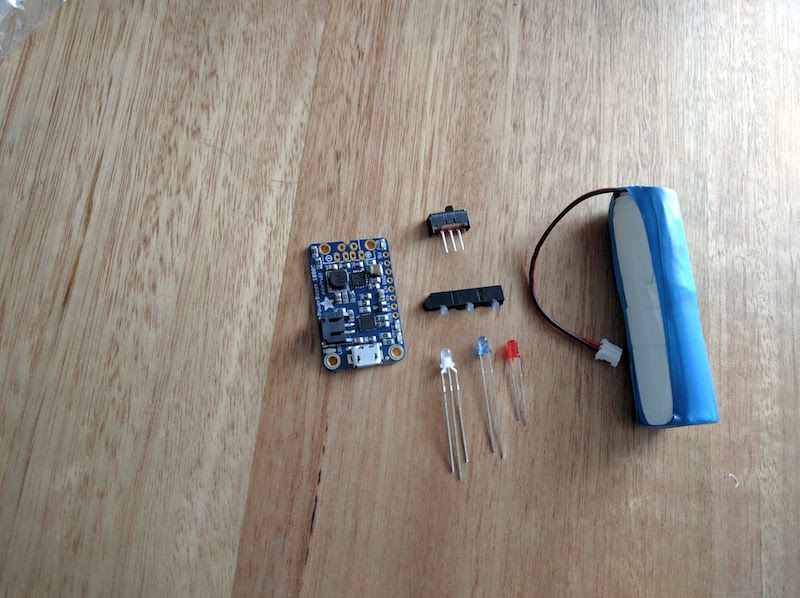
It’s been quite a few weeks from my last update. Life and work got on the way of this project but I’m back on it, I also received some of the parts that I was waiting so I could start doing the power section of this project.
@jb3264 thanks for the head ups as @Marchioly mentioned I will definitely power it up from the power strip.
I have been thinking from a few month ago about a way to see the battery status. The cool thing is that the 3ds replacement case came with the light diffuser which fit at the front of the case.
So with this in mind I did a bit of research on the powerboost 1000C board to find a way to do a break board with some LED sitting under the diffuser.
What I’m thinking to use from the board is the Red LED for lower battery, the yellow LED for the charging state and the green LED for the charged state.
On the powerboost board the green and yellow LED share the V line and therefore can but wired to a RGB LED or a Bi-Color LED which has a common anode. I also test the voltage from the onboard LED and they run on 1.94v.
After doing some research I stumble onto this Bi-colour LED which match the colour I wanted to display, green and orange and also run between 1.9v to 3.8v which sounded perfect.
https://www.aliexpress.com/item/Common- ... 0.0.I96eme
So fast forward, I finally got those LEDs and it was play time during the weekend
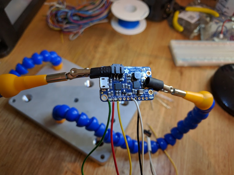
I wired the cable directly on top of the on board LED solder pad with the help of some flux
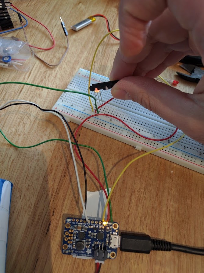
And with the help of a breadboard I could test the LED

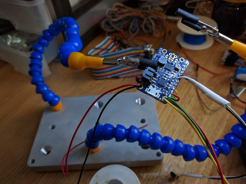
And lastly I solder the wired for the red LED which I will test in the future
On the case side I'm doing the few different ports. I will be posting this in my next update and I'm also get a frankencasing guide ready that I will be posting soon.
@jb3264 thanks for the head ups as @Marchioly mentioned I will definitely power it up from the power strip.
I have been thinking from a few month ago about a way to see the battery status. The cool thing is that the 3ds replacement case came with the light diffuser which fit at the front of the case.
So with this in mind I did a bit of research on the powerboost 1000C board to find a way to do a break board with some LED sitting under the diffuser.
What I’m thinking to use from the board is the Red LED for lower battery, the yellow LED for the charging state and the green LED for the charged state.
On the powerboost board the green and yellow LED share the V line and therefore can but wired to a RGB LED or a Bi-Color LED which has a common anode. I also test the voltage from the onboard LED and they run on 1.94v.
After doing some research I stumble onto this Bi-colour LED which match the colour I wanted to display, green and orange and also run between 1.9v to 3.8v which sounded perfect.
https://www.aliexpress.com/item/Common- ... 0.0.I96eme
So fast forward, I finally got those LEDs and it was play time during the weekend
I wired the cable directly on top of the on board LED solder pad with the help of some flux
And with the help of a breadboard I could test the LED
And lastly I solder the wired for the red LED which I will test in the future
On the case side I'm doing the few different ports. I will be posting this in my next update and I'm also get a frankencasing guide ready that I will be posting soon.
Who is online
Users browsing this forum: No registered users and 1 guest