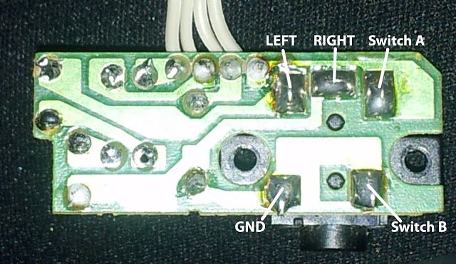
This is the pinout for the original jack, notice the 2 switch pads A and B.
This was how I did the GB jack setup:

You need to desolder Switch B so that it no longer has contact with Ground. Switch B is connected to Switch A, but only when no plug is connected. Red wire is (+) going to the speaker and black wire is (-) going to ground. Blue wire is from USB audio to L+R (I did mono sound to headphone rather than stereo. You can theoretically do stereo but the sound going to speaker will be mono). Blue/white wire is ground from USB audio. The orange wire is a bridge for L+R to Switch B. This means under normal conditions, the signal will go all the way to speakers but when headphone jack is inserted, the connection between Switch B and Switch A is cut, providing only signal to headphones.
EDIT: Ok guys, finally had some free time so I'm adding the wiring schematic I used in full here. This includes a pot that will control both speaker and headphone volume as well as the addition of the Adafruit amp.
- SoundSetup.png (35.16 KiB) Viewed 15096 times


