Display flicker

Having trouble with your GBZ build? Ask your questions here!
Serinbre
Posts: 5
Joined: Sun Feb 03, 2019 11:55 pm

Display flicker

Post by Serinbre » Mon Feb 04, 2019 12:07 am

Image
I’ve been working at this display for a good 5 hours.
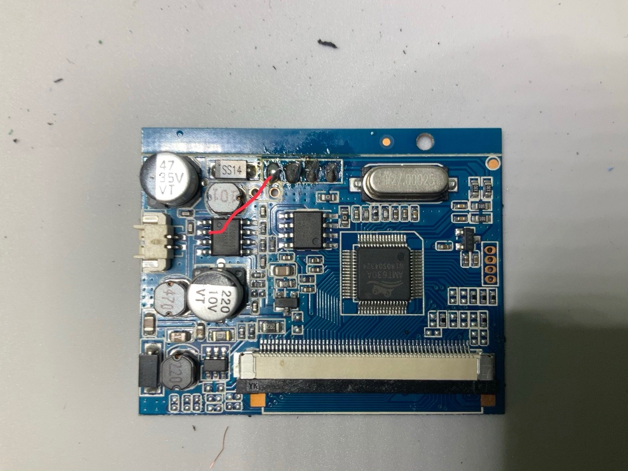
I’ve tried replacing the wires, resoldering, etc.
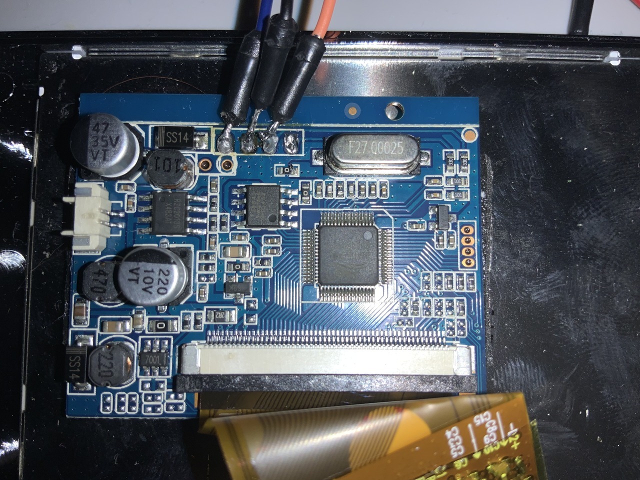
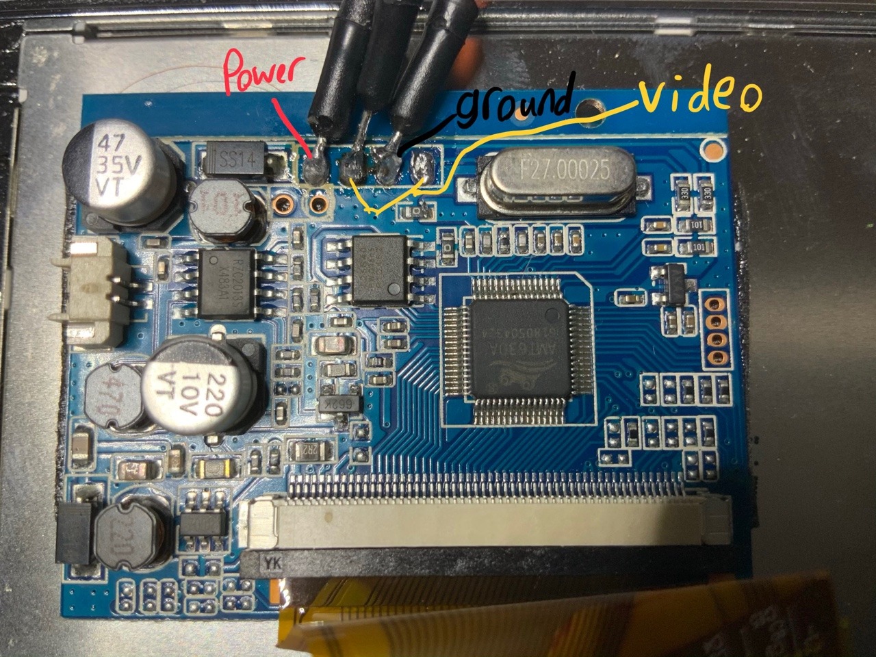
I found the wiki and realized that it’s most likely not working at 5v but I couldn’t find this board type on it.
If anyone knows how to make it work at 5v or if it’s something else I need to do.
Any help would be appreciated, thanks.

User avatar
tinkerBOY
Posts: 710
Joined: Tue May 30, 2017 4:00 am
Has thanked: 294 times
Been thanked: 206 times

Re: Display flicker

Post by tinkerBOY » Mon Feb 04, 2019 2:45 am

Take some closeup pictures of the board so we can check which part is the 5v regulator.
New! tinkerBOY PowerSwitch v1.0 with Safe Shutdown
Game Boy Zero Controllers available @ tinkerBOY.xyz * Support
tinkerBOY Controller v3.0 - built-in usb controller, usb audio, and usb hub
tinkerBOY Controller v2.0 - GPIO buttons and builtin PWM Audio and Amplifier
tinkerBOY Controller v1.1 - simple pcb button
* DPI Adapter - better display for GBZ
* keyboard converters - IBM XT/AT Soarer's Converter | ADB to USB Converter

Serinbre
Posts: 5
Joined: Sun Feb 03, 2019 11:55 pm

Re: Display flicker

Post by Serinbre » Mon Feb 04, 2019 4:06 am

Image
Image
Image

User avatar
infinitLoop
Posts: 536
Joined: Mon Dec 24, 2018 11:46 am
Location: Portland, OR
Has thanked: 222 times
Been thanked: 199 times
Contact:

Re: Display flicker

Post by infinitLoop » Mon Feb 04, 2019 10:28 am

i don't think your wires are correct. the video are the two connectors on the right side (looking at the picture). the ground is the second one from the left. so, it's: VIN, GND, AV2, AV1

i've used a couple of this model, and it should work without the 5v mod if you have it connected to the correct inputs, but you can also do the 5v mod to the chip that is underneath the (upside-down) "101" inductor, with the "RZC2013S" on it. i was able to get it working with by tapping into pin 3, but pin 2 i think is the correct one. that is the second pin down from the left (just below where the dot is on the chip) for pin 2 or the next one down for 3.
Last edited by infinitLoop on Mon Feb 04, 2019 3:30 pm, edited 1 time in total.

Serinbre
Posts: 5
Joined: Sun Feb 03, 2019 11:55 pm

Re: Display flicker

Post by Serinbre » Mon Feb 04, 2019 11:10 am

When the raspberry pi is powered on the screen flickers. I can see the retro pie boot screen but it turns on for a second then powers off then comes back on after 2 seconds then goes off. The pi zero boots up fine, it’s just having the screen stay on for more than a second at a time.

User avatar
correia5022
Posts: 202
Joined: Mon Dec 05, 2016 12:32 am
Location: Portugal
Has thanked: 17 times
Been thanked: 38 times

Re: Display flicker

Post by correia5022 » Mon Feb 04, 2019 1:10 pm

Serinbre wrote:
Mon Feb 04, 2019 11:10 am
When the raspberry pi is powered on the screen flickers. I can see the retro pie boot screen but it turns on for a second then powers off then comes back on after 2 seconds then goes off. The pi zero boots up fine, it’s just having the screen stay on for more than a second at a time.
So probably its not getting enough voltage. You must mod it.
Also i agree with infinitLoop, the wiring is wird for me, never seen that combination, where the video is in the middle of vcc and gnd... can you take a picture of the other side of the pcb. Also follow infinitLoop instruction to mod it and try it.
________________________________________
Starting on electronics :)
My first build, 2 years later
https://sudomod.com/forum/viewtopic.php ... 8&start=30
Check out my Boombox: https://nrcboombox.wixsite.com/website

User avatar
infinitLoop
Posts: 536
Joined: Mon Dec 24, 2018 11:46 am
Location: Portland, OR
Has thanked: 222 times
Been thanked: 199 times
Contact:

Re: Display flicker

Post by infinitLoop » Mon Feb 04, 2019 3:26 pm

here a (blurry) pic of one that i had working fine with a rpi0 and a powerboost:
SpoilerShow
IMG_5116.jpg
IMG_5116.jpg (654.86 KiB) Viewed 7161 times
i also have one working that is just wired directly to the pin on the chip, but that's in a gb that is closed up at the moment

Serinbre
Posts: 5
Joined: Sun Feb 03, 2019 11:55 pm

Re: Display flicker

Post by Serinbre » Mon Feb 04, 2019 4:29 pm

Im going to try the connection you did but I’m trying to figure out which pin you hooked it to
Was it 1 Image
Or 2 Image

User avatar
infinitLoop
Posts: 536
Joined: Mon Dec 24, 2018 11:46 am
Location: Portland, OR
Has thanked: 222 times
Been thanked: 199 times
Contact:

Re: Display flicker

Post by infinitLoop » Mon Feb 04, 2019 5:28 pm

Serinbre wrote:
Mon Feb 04, 2019 4:29 pm
Im going to try the connection you did but I’m trying to figure out which pin you hooked it to
Was it 1
Or 2
well, that's the rub... i actually used in 3 (picture 1) but tinkerboy (who i would trust over me on this) said pin 2 (picture 2) in another post, so take that however you want. based on my experience, you at least cannot ruin it by doing pin 3, so you could maybe try that first.


Post Reply

Who is online

Users browsing this forum: No registered users and 1 guest