Ok so firstly I mean no disrespect posting for or linking to another forum, so I hope its ok. Adam (othermod) over at othermod.com has built a Pi PSP and its great, hes currently revamping it and is pretty new to custom PCB design (and I know nothing about it). I told him that some of the guys here on sudomod made awesome stuff for Wermy's GameBoy Zero.
I know he could use the help if any designers wanted to check it out.
http://othermod.com/community/pspi-disc ... connector/
Pi in a PSP
-
johnweland

- Posts: 26
- Joined: Tue May 10, 2016 12:11 pm
- Has thanked: 3 times
- Been thanked: 8 times
- Contact:

Re: Pi in a PSP
Nice find! Perhaps @Camble, @Kite, or @Helder are willing to help out. I know they're all pretty busy though.
PS: We're happy to have any similar content on the forums as long as everyone here is civil/helpful.
PS: We're happy to have any similar content on the forums as long as everyone here is civil/helpful.
Last edited by a3k4 on Thu Aug 25, 2016 7:52 am, edited 1 time in total.
My wiring diagrams and schematics for Helder's boards and graceful shutdowns.
-
kite

- Posts: 972
- Joined: Thu May 12, 2016 4:30 am
- Location: UK
- Has thanked: 246 times
- Been thanked: 361 times
- Contact:
Re: Pi
If he has specific questions sure go for it! If he posted his work in progress and schematics we can comment
Stock clearance - CLOSED: viewtopic.php?f=38&t=12064
Kite's Mailing List: https://goo.gl/forms/e97uUvPOfUxPWdz82
Kite's FAQ: https://kiteretro.com/faq/


Kite's Mailing List: https://goo.gl/forms/e97uUvPOfUxPWdz82
Kite's FAQ: https://kiteretro.com/faq/
-
othermod

- Posts: 43
- Joined: Wed Aug 03, 2016 7:03 pm
- Location: https://t.me/pump_upp
- Has thanked: 6 times
- Been thanked: 21 times
- Contact:
Re: Pi in a PSP
Hey guys,
johnweland referred me to this forum, and I see he already got the conversation started for me.
For a little background, I've been working on a Pi Zero project for a few months that I call the PSPi. I took the internals out of a dead PSP and replaced them with a Pi Zero and all new components. Some of the components were purchased on eBay and some were custom-made. The project was inspired by Wermy and his Gameboy when I saw his Youtube videos a while back. I didn't realize he had a site and such a following until someone over here linked to my tutorials.
So anyway back to the reason I'm here. One part of the project required me to interface an FPC 24-pin cable with the Pi Zero, and I did this by separating and soldering each wire individually to the Pi. This was very difficult, and I've had many people tell me that they love the project and want to make one, but that this is beyond their ability. So, after being asked by multiple people, I've decided to try to design a board that the PSP's FPC cable will connect to directly, and that will have a 40-pin header to connect to the GPIO on the Pi. Since I'm doing all that, it also makes sense to add the FPC 10-pin connector, power circuit, and low-battery circuit to the same board.
I'm learning to use Eagle, and I've got a design coming together. I'll post a link to the file once I get it uploaded. Does anyone with PCB design experience have interest in getting involved?
If so, I need:
The name of a PCB manufacturer (US preferred but not required) that has decent prices
Help converting Eagle files to Gerber layer files that can be submitted to PCB makers
Feedback on the design I'm working on
Any help anyone is willing to offer
-
kite
- Posts: 972
- Joined: Thu May 12, 2016 4:30 am
- Location: UK
- Has thanked: 246 times
- Been thanked: 361 times
- Contact:
Re: Pi
Greetings!othermod wrote:#1 The name of a PCB manufacturer (US preferred but not required) that has decent prices
#2 Help converting Eagle files to Gerber layer files that can be submitted to PCB makers
#3 Feedback on the design I'm working on
#4 Any help anyone is willing to offer
1 - OSHPark is good
2 - Open brd -> CAM processor -> load -> {insert gerber cam file here, eagle has some but you can get it from OSHPark or your fab house}.
Not really needed anyway for OSHPpark as you can upload .BRD directly
3 - Show us some pics
4 - Everyone loves helping
Stock clearance - CLOSED: viewtopic.php?f=38&t=12064
Kite's Mailing List: https://goo.gl/forms/e97uUvPOfUxPWdz82
Kite's FAQ: https://kiteretro.com/faq/
Kite's Mailing List: https://goo.gl/forms/e97uUvPOfUxPWdz82
Kite's FAQ: https://kiteretro.com/faq/
-
othermod
- Posts: 43
- Joined: Wed Aug 03, 2016 7:03 pm
- Location: https://t.me/pump_upp
- Has thanked: 6 times
- Been thanked: 21 times
- Contact:
Re: Pi in a PSP
Thank you kite. That's great that OSHPark takes the .BRD files.kite wrote: 1 - OSHPark is good
2 - Open brd -> CAM processor -> load -> {insert gerber cam file here, eagle has some but you can get it from OSHPark or your fab house}.
Not really needed anyway for OSHPpark as you can upload .BRD directly
3 - Show us some pics
4 - Everyone loves helping
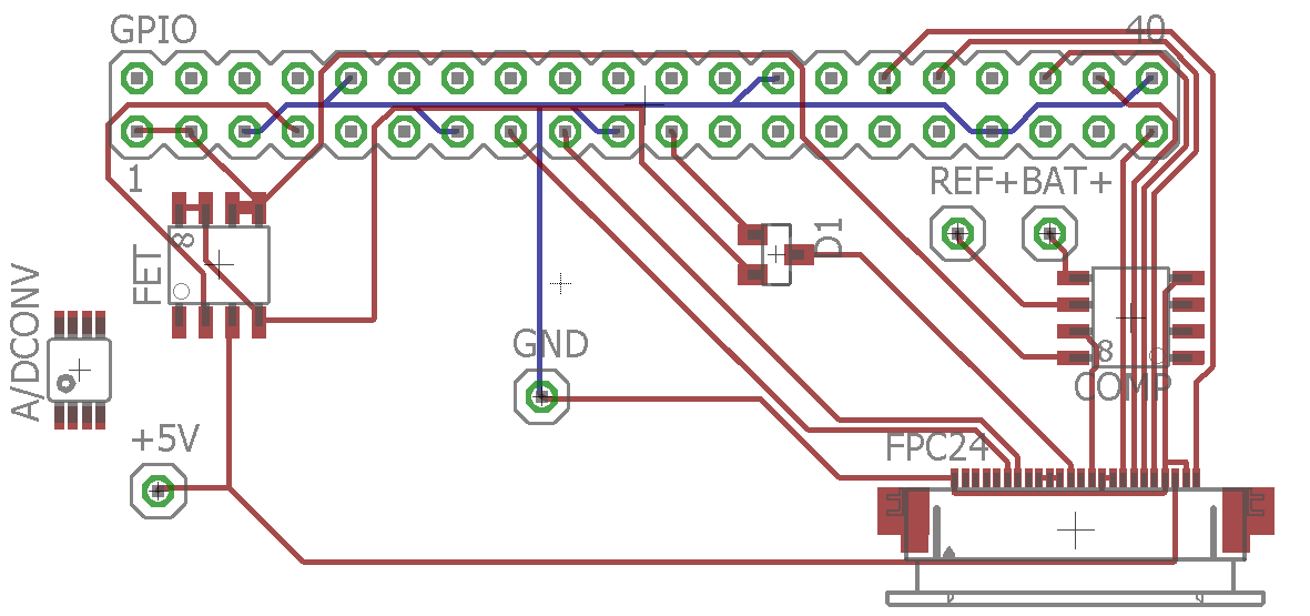
Here is the most recent screenshot of the progress. The position of the components is changing as I take measurements and make adjustments. Ideally the new board would fit into the same area as the original board, but that's a lot of square inches, so my focus is just on getting something that will connect up.
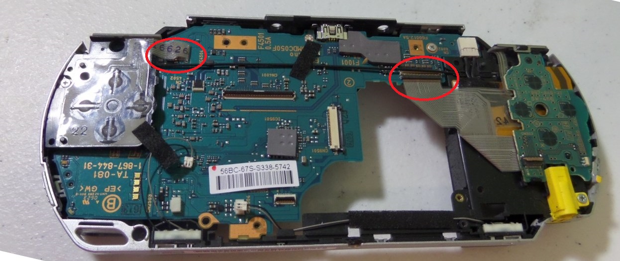
Here is an image of the board. The two FPC connectors are circled.
Last edited by othermod on Fri Aug 26, 2016 9:53 am, edited 1 time in total.
-
kite
- Posts: 972
- Joined: Thu May 12, 2016 4:30 am
- Location: UK
- Has thanked: 246 times
- Been thanked: 361 times
- Contact:
Re: Pi
Looks interesting!othermod wrote:...
A few things to note:
- Use a ground plane, rather than routing ground to each place (google this)
- Any power carrying make as thick as needed.. thin wires don't carry a lot of power and work for signal wires, but 5V wires need to be a lot thicker. For example power going from the 5V pin, through the fet, into the Pi (and presumably powering it?) will have a TERRIBLE job at it and it will probably reset itself all the time
- Wherever you use power to an IC, you should use a 'decoupling capacitor' which basically means put a small (1uF) capacitor RIGHT NEXT to the component, connecting the 5V and GND.. EVERY component that uses power needs one of these, so you end up with capacitors right next to all the components. Anything that is power hungry (regulator, SD card, etc) needs a way bigger capacitor (4.7uF/10uF)
Stock clearance - CLOSED: viewtopic.php?f=38&t=12064
Kite's Mailing List: https://goo.gl/forms/e97uUvPOfUxPWdz82
Kite's FAQ: https://kiteretro.com/faq/
Kite's Mailing List: https://goo.gl/forms/e97uUvPOfUxPWdz82
Kite's FAQ: https://kiteretro.com/faq/
-
othermod
- Posts: 43
- Joined: Wed Aug 03, 2016 7:03 pm
- Location: https://t.me/pump_upp
- Has thanked: 6 times
- Been thanked: 21 times
- Contact:
Re: Pi in a PSP
I'm researching how to set up a ground plane now. Seems smarter.kite wrote:[
- Use a ground plane, rather than routing ground to each place (google this)
- Any power carrying make as thick as needed.. thin wires don't carry a lot of power and work for signal wires, but 5V wires need to be a lot thicker. For example power going from the 5V pin, through the fet, into the Pi (and presumably powering it?) will have a TERRIBLE job at it and it will probably reset itself all the time
- Wherever you use power to an IC, you should use a 'decoupling capacitor' which basically means put a small (1uF) capacitor RIGHT NEXT to the component, connecting the 5V and GND.. EVERY component that uses power needs one of these, so you end up with capacitors right next to all the components. Anything that is power hungry (regulator, SD card, etc) needs a way bigger capacitor (4.7uF/10uF)
10-4 on wire width. I'm just letting autorouter do its thing until I get component location right.
I can see the capacitor being very helpful on the power mosfet. I've never seen the term 'decoupling capacitor' before, but I definitely used one in my car when I was younger.
-
Helder

- Trailblazer

- Posts: 2985
- Joined: Thu May 05, 2016 8:33 am
- Location: Rogers, AR
- Has thanked: 1459 times
- Been thanked: 3114 times
Re: Pi in a PSP
Do you have an idea of how and where you want to mount this? having an idea of placement helps in getting a board shape made and also where you can put components so it all ties in easily. Some if not many of those extra components you used like the Amp can all be integrated into this board, hell even the power board can be done too but might be cheaper as you have it now.
Chat with me and other members On Discord
Don't contact me about obtaining my board files (as you will not get them). If my Boards or PCB Kits are sold out, they will be restocked as soon as I can get them and there is demand for them. You can join the mailing list on my Website to be notified when they are available.
Helder's Game Tech Website
We will not support any cloned work so don't come to us with technical issues to resolve, go talk to the cloner for help.
-
othermod
- Posts: 43
- Joined: Wed Aug 03, 2016 7:03 pm
- Location: https://t.me/pump_upp
- Has thanked: 6 times
- Been thanked: 21 times
- Contact:
Re: Pi in a PSP
I do. I've got some constraints on shape and size because of the positioning of the LCD driver and Pi (both of these parts cannot be moved from where they are), so that's the main pieces I'm working around. I plan to post an update with far more specific details once I get off work this afternoon. You're definitely right when you say that other parts (like audio amp) can be added. I'm taking baby steps right now and trying to keep it simple, but that might get added if I can get everything else added successfully. The power board is beyond my abilities (way beyond), so someone more skilled would have to help if they wanted that included.Helder wrote:Do you have an idea of how and where you want to mount this? having an idea of placement helps in getting a board shape made and also where you can put components so it all ties in easily. Some if not many of those extra components you used like the Amp can all be integrated into this board, hell even the power board can be done too but might be cheaper as you have it now.
Who is online
Users browsing this forum: No registered users and 1 guest