Sorry for the late reply guys. I'm swamped with work on my day job and has not had the time lately to visit the forums. Nways...
@Retrohead95
I just cut the hole using the pin vise + jeweler's saw technique then widened the hole slowly using a set of needle files.
@Deadtime
Yes, it can be done.

@yves1984
Thanks! I have not done any shopping list but would probably do later.
@Fleder
Nice! I see you're also cutting using the pin vise technique? How do you find it so far?
@wesker16
I will not recommend if you only need the SNES controller and still connect it to the Teensy. There's better controller board being sold in this forum that is easier to solder on.
@Ganreizu
See my reply below:
Can you elaborate more on this audio option?
[Chiz] sure
Specifically:
How does it fit in the case? Is it obnoxiously big or is it a good fit?
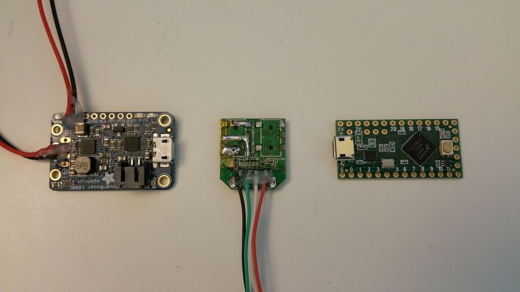
[Chiz] The USB audio board is quite small. I will post pics later
Can we still use a volume wheel?
[Chiz] I probably will not be using the original GB wheel with the board. I'm thinking of using the space where I removed the mic jack in the USB audio board.
Will the speaker go mute when headphones are plugged in?
[Chiz] This can be done if you use a stereo jack with disconnect feature.
What speaker should we use that will fit in the case's speaker mold?
[Chiz] You can use the original GB speaker or any 8ohm micro speaker that would fit in the speaker cavity. I'm waiting for a 2w micro speaker to see if it will sound louder.
Do we give up usb bluetooth's usb port for this?
[Chiz] To be honest, Bluetooth for me is not necessity and in the event I'll need it, I will just use the exposed/external USB port that I will attach in the internal hub.
I really want to use this option for audio; sounds very easy and no mess. I feel like we would have to take it apart to get a volume wheel though, and i feel like space is a concern. Then again i'm using a RPI0 and you're using a far larger RPI2B+ so i guess it's not so bad?
[Chiz] Personally, I find the using the USB audio easier to implement than going the PWM route. I will post a reference on how to use a USB audio.
@Rod2D2/@Camble
You are correct. I used
modelling styrene. However, you can use old credit/gift cards that you no longer use,