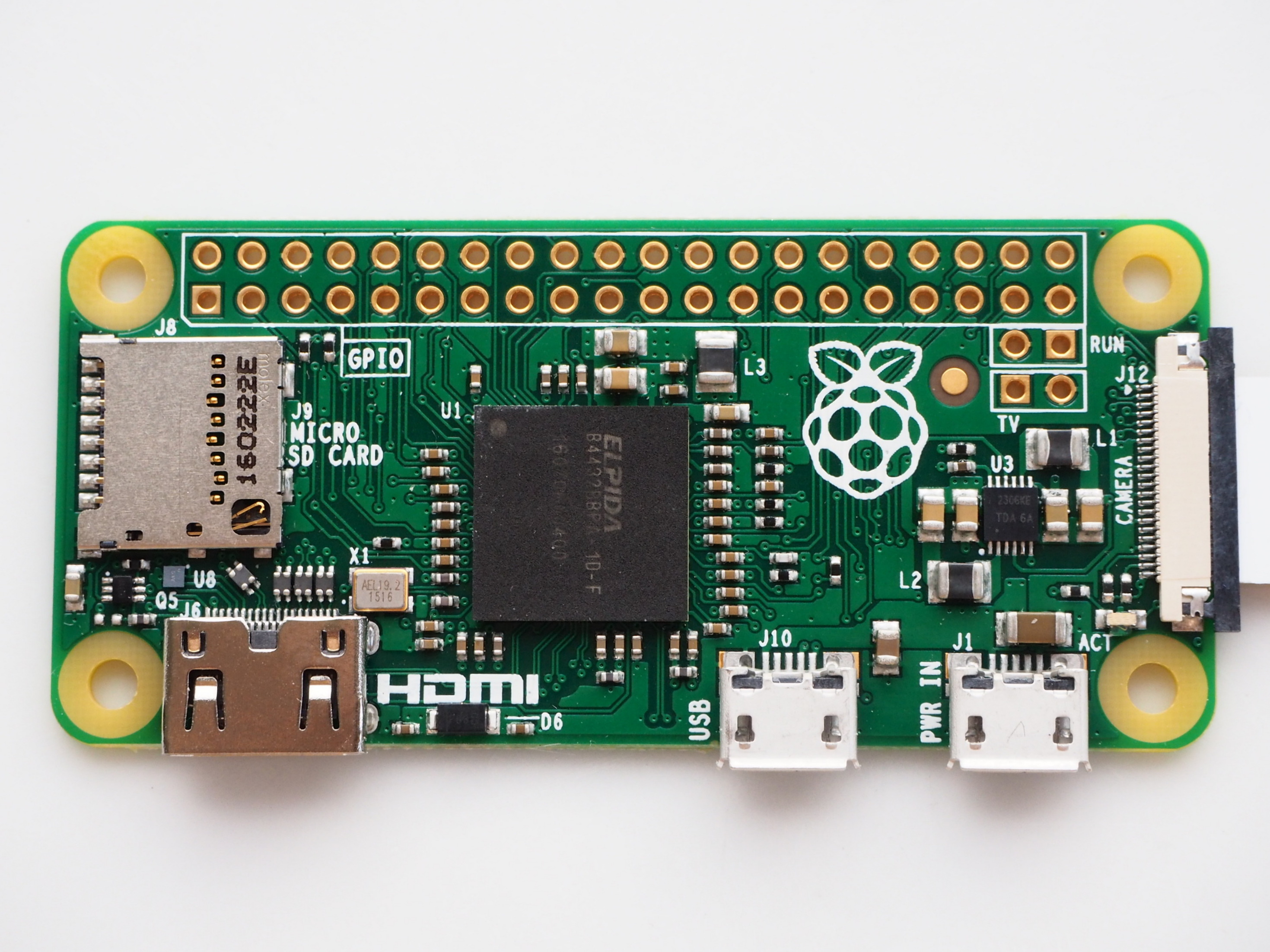
Hey Guys I just started this project. I am extremely inspired by this forum and I believe that with your help I can do this, so I have raspberry pi zero and cheap chinese made LCD https://www.amazon.com/dp/B0045IIZKU/re ... UTF8&psc=1
I don't know what I am doing wrong but when I plug raspberry pi to the power source , the screen of LCD is still black it seems like I connected it all wrong, so please take a look at the pictures and give me your suggestions
http://imgur.com/a/NryT2
LCD -- Pi Zero HELP
-
Tamasco

- Posts: 67
- Joined: Tue Jun 21, 2016 2:37 pm
- Location: Spain
- Has thanked: 34 times
- Been thanked: 10 times
Re: LCD -- Pi Zero HELP
First of all, I think you are connecting the TV and ground wires incorrectly. You are connecting them to PP4 and PP9, which are not the TV and Ground GPIO in you PI0 1.2. They are just above those.

Secondly, be really carefull where do you connect the current to. Read my thread to learn from my mistake. I just burned a Pi0:
http://www.sudomod.com/forum/viewtopic.php?f=23&t=687
You can see there instructions on how you should connect the display, by @Felder.

Thirdly. Please @Felder , correct me if I´m wrong. I can see in your picture that you are connecting yellow and white wires, but both of them are TV signals (AV1/AV2). You just need to connect one of them. You can just also use one ground (the black one you already have). Also, as I have recently been said, you should connect the red wire, 5v, to the GPIO, which can be number 2 or 4:
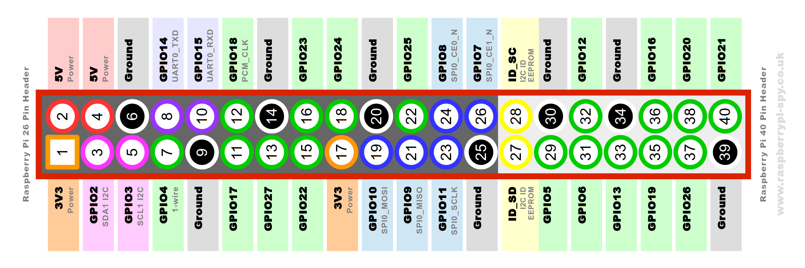
Edit: Could you say which is the order of the wires from your board? White, black, yellow, and red? I´m not really sure, but if this is the order, I think you are using black wire as ground, and it should be AV2.
Please, someone correct me.
Secondly, be really carefull where do you connect the current to. Read my thread to learn from my mistake. I just burned a Pi0:
http://www.sudomod.com/forum/viewtopic.php?f=23&t=687
You can see there instructions on how you should connect the display, by @Felder.
Thirdly. Please @Felder , correct me if I´m wrong. I can see in your picture that you are connecting yellow and white wires, but both of them are TV signals (AV1/AV2). You just need to connect one of them. You can just also use one ground (the black one you already have). Also, as I have recently been said, you should connect the red wire, 5v, to the GPIO, which can be number 2 or 4:
Edit: Could you say which is the order of the wires from your board? White, black, yellow, and red? I´m not really sure, but if this is the order, I think you are using black wire as ground, and it should be AV2.
Please, someone correct me.

Re: LCD -- Pi Zero HELP

like this, also did you confirm your screen worked correctly from 5v first?
http://sudomod.com/game-boy-zero-guide-part-3/
Re: LCD -- Pi Zero HELP
@Tomasco so the order on my board counting from the left side goes :white, yellow,black,red
and here I also add the picture so you can see better , I desoldered all my wired and soldered it again accordingly yo your schematic
http://imgur.com/BeHiNmD
and here I also add the picture so you can see better , I desoldered all my wired and soldered it again accordingly yo your schematic
http://imgur.com/BeHiNmD
-
Tamasco
- Posts: 67
- Joined: Tue Jun 21, 2016 2:37 pm
- Location: Spain
- Has thanked: 34 times
- Been thanked: 10 times
Re: LCD -- Pi Zero HELP
Is it working now?acmaciek wrote:@Tomasco so the order on my board counting from the left side goes :white, yellow,black,red
and here I also add the picture so you can see better , I desoldered all my wired and soldered it again accordingly yo your schematic
http://imgur.com/BeHiNmD

-
Tamasco
- Posts: 67
- Joined: Tue Jun 21, 2016 2:37 pm
- Location: Spain
- Has thanked: 34 times
- Been thanked: 10 times
Re: LCD -- Pi Zero HELP
Theorically you have them right. You sure that the screen works with 5v?acmaciek wrote:Check the pictures I posted please . I still can't seem to figure it out
Re: LCD -- Pi Zero HELP
your soldering needs cleaned up its hard to see if you bridged something also if you still have it was your chip a XL1509 please post exactly what was on it.acmaciek wrote:Check the pictures I posted please . I still can't seem to figure it out
http://www.xlsemi.com/datasheet/XL1509%20datasheet.pdf
also if nothing you can do gets it to come on you could try a 5v to 12v step up, something like this maybe http://www.ebay.com/itm/5W-DC-DC-Boost- ... 1549196955
Update:
ok i think i may have found what your looking for
this board wont turn on without a video signal so make sure you dont have the video and ground reversed
Who is online
Users browsing this forum: No registered users and 1 guest