Misc guides
Contents
Raspberry Pi Zero Pinouts
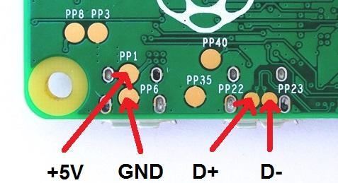
USB Data & Power Solder Points
Potential fix for USB pad problems
Forum user PotaTox added this guide as a potential fix for USB pad problems see the thread here
So, recently I became stuck on part six of Wermy's guide because for whatever reason, the USB test pads on the pi outright refused to work, no matter what I threw at it. However, it worked when I plugged in with an OTG cable. So, I thought "What are differences between using wires rather than an OTG cable?", and I figured it out.
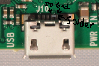
Mini and Micro USB have an extra pin, called ID. When you use an OTG cable, the cable grounds that ID pin. So, you need to ground that pin. What I did is I put a bit of solder on the surface mount pins for the micro usb port, and poof it worked :D PolletjeNL said that putting a small cable between test pad 35 and 40 gives the same result, since they are connected to the micro-usb port's pins. You can use whichever method you want, since the end result is the same.
I made a really poor diagram of it.
You may notice that the topic says potential fix. That is because I don't know if it's just my Rpi Zero, or why I had to do it while Wermy didn't. If you can't get your hub to work, try this. It may help.
Power optimization
Forum User Yaya has an excellent power management and optimization post located here on the forums. The simple and easy tweaks are listed below, but there are a couple more in his post for the more adventurous.
Note that these optimizations assume SSH or CLI access.
Quick Nano guide:
- Arrow Keys to move around as expected
- Ctrl-W to find (Where is)
- Ctrl-O to save (Write Out)
- Ctrl-X to Exit (will be prompted to save on exit, press 'n' to exit without saving)
- On Windows using Putty SSH client, 'paste' is performed by right-clicking with the mouse anywhere in the window, the contents of the clipboard will be pasted at the current cursor location
Disable Samba
If you do not use Samba (Windows File Sharing) to add/backup ROMS, then you can disable it:
sudo ~/RetroPie-Setup/retropie_setup.sh
- Choose C : Configuration / tools
- Choose 828 : Samba
- Choose 2 : Remove Samba Shares
- Choose 5 : Remove Samba
Disable ROMService
If you do not use the USB Flash/Thumb drive service, then you can disable it:
sudo ~/RetroPie-Setup/retropie_setup.sh
- Choose C : Configuration / tools
- Choose 835 : usbromservice
- Choose 2 : disable usbromservice scripts
Disable TV and HDMI signals
If you are using an SPI or DPI display (such as Kite's AIO or the MintyPi) then you can disable HDMI and Composite/TV circuits:
DO NOT perform this step if you use an HDMI or Composite (such as the GearBest, Adafruit, or BW) screen
/usr/bin/tvservice -o
To disable (will re-enable on reboot).
/usr/bin/tvservice -p
To re-enable (Often breaks and wont re-enable composite, just reboot).
To make permanent:
sudo nano /etc/rc.local
At the bottom, add:
/usr/bin/tvservice -o
Disable Pi Status LEDs
sudo nano /boot/config.txt
At the bottom, add:
##########################
#### DISABLE PI STATUS LED ######
##########################
dtparam=act_led_trigger=none
dtparam=act_led_activelow=on
Improve SD Performance
sudo nano /boot/cmdline.txt
Find: elevator=deadline
Change to: elevator=noop
Do not add any extra line breaks, or your Pi may not boot. You can make this edit on a Windows PC viewing the SD card, so make a backup before).
Adjust Swap
To be nicer to the SD card, and to make better use of available RAM, only use swap when its needed.
sudo nano /etc/sysctl.conf
At the end, add:
vm.swappiness = 1
Tweak Filesystem for fewer writes
By default Retropie will write a tiny bit of metadata to the SD card every time a file is even viewed. On write sensitive flash media, this is wasted power and life-shortening.
sudo nano /etc/fstab
Locate the line containing the text /boot. It will normally be the 2nd one. On the same line, find the word defaults.
Change to: defaults,noatime. The 3rd line may already have it, if so, mimic it.
Example:
proc            /proc           proc    defaults          0       0
/dev/mmcblk0p1  /boot           vfat    defaults,noatime          0       2
/dev/mmcblk0p2  /               ext4    defaults,noatime  0       1
# a swapfile is not a swap partition, no line here
#   use  dphys-swapfile swap[on|off]  for that
Disable Avahi service
Windows Users wont notice this most likely, but Mac & linux users might. With this service disabled you'll need to SSH in using the DNS hostname or the IP adress rather than the simpler 'pi.local' short name.
sudo apt-get purge avahi-daemon -y
Disable Wireless Systems
If not being used, you can disable the on-board Wifi & Bluetooth of the Pi3 and Zero W to save power.
sudo nano /boot/config.txt
At the bottom, add:
Wifi
##########################
#### DISABLE Wifi ######
##########################
dtoverlay=pi3-disable-wifi
Bluetooth
#########################
#### DISABLE BLUETOOTH ######
##########################
dtoverlay=pi3-disable-bt
Progressive scan on composite
Forum user mariovisic added a great guide to enable progressive scan on composite, below is the guide (there's more posts about tuning this setting at the thread)
The pi never used to be able to output a progressive signal over the composite output, but in March it received an update to allow it to work :) You can see the discussion about it at Github
On a CRT display you would get a stable image and nice scanlines but on my LCD display it doesn't produce scanlines, it does however stabilise the image dramatically. No more shakey text and shimmering sprites.
Here's how you go about it.
Firstly update your Pis firmware to the latest stable version by running
sudo apt-get update; sudo apt-get dist-upgrade
Once you're running the latest version you can add the following line to your /boot/config.txt:
sdtv_mode=16
You can check its working by running:
tvservice -s
The output should look like:
state 0x40001 [NTSC 4:3], 720x480 @ 60.00Hz, progressive
Headphone Jack Pinouts
A forum user has made a great headphone jack pinout guide here on the forums
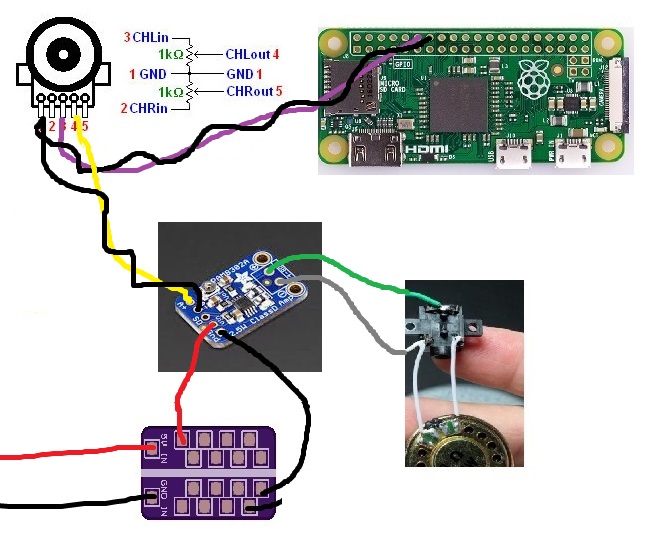
PWM Audio wiring diagram
rodocop made a wiring diagram to set (mono) PWM audio
How to Test for Speaker Wire Polarity
dryja123 has found this great guide
You'll need:
- Nine-volt battery
- Electrical tape
- Marking tool
- Multimeter
It’s important that your speakers are wired to the right polarity to achieve the best sound quality possible, and obviously, failure to do so will produce lower quality sound that you've paid too much to deal with. So, if you're having problems with getting good, clear sound out of your speakers, it's time to test whether mixed up wiring is the cause. There are commercial devices that can check for speaker wire polarity, but using these steps, you can do it yourself without spending extra money.
Step 1 - Disconnect
Begin by unplugging your stereo system at the outlet. You should also remove any wires that connect the system to other devices, such as a television. Then, once you're sure power is completely off, disconnect the wires of one speaker from the receiver. You will also need to remove the cover on the front of the speaker so you can see the speaker cone.
Step 2 - Adjust to View Speaker Cone
You won’t always be able to see the speaker cones; not all covers are removable, which is particularly true with a subwoofer. If this is the case, you need to position the speaker so you can see through the grille to view the cones. It makes the task a little harder, but far from impossible.
Step 3 - Test With Your Battery
You will want a fully-charged nine-volt battery for this test, so just use a new battery to eliminate any guess work.
Take the speaker wires and wrap one around each of the terminals on the battery. Now, look at the speakers cones closely. The current from the battery will cause movement in them, and you'll will need to note how they move; the cone should go outward and then in. If it does this, the polarity is correct. However, if the movement is inward first, swap the wires around on the battery and look again. This time, it should be correct. These motions can be hard to distinguish immediately, so be vigilant and watch carefully.
Once you're sure of the proper polarities, use something like electrical tape to mark the wires properly. Then, you can reconnect them to the receiver, with the wire from the positive terminal on the battery going into the red terminal and the negative going to the black.
Step 4 - Try to Test With a Multimeter
If the movement test can't be conducted, you can use a multimeter test instead. Start by removing the speaker wires from both speaker and receiver. Then, set yourself up so one wire is wrapped around each terminal of the battery.
Set the multimeter to measure DC voltage, and touch the speaker wires to the probes. If your probe is touching a wire with an opposite polarity, such as the positive probe to a negative wire, you will get a negative numerical reading. Try switching which probe you're using to get a positive reading instead. This will allow you to mark which wire is which and reconnect them to your speakers properly.
Tip: You do need a current in order to measure with a multimeter, so having the battery is vital. You also need to be sure that you don’t measure from the receiver.
Listen to the speakers after you’ve established the correct polarity, and you’ll be able to readily hear the difference!
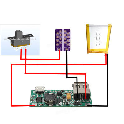
Banggood Power Boost Wiring Diagram
Forum user RetroGamingNow made a wiring diagram for Banggood power boost (without safe shutdown switch), you can follow the thread here


